Reciprocating rotary piston system and pressure pump and IC engine using same

A reciprocating rotation and rotary power technology, which is applied in the direction of rotary piston engines, rotary or swing piston engines, swing piston pumps, etc., can solve the problems of shortened life, unavoidable piston force or reaction force, excessive wear, etc., to achieve Vibration and noise reduction effect

Inactive Publication Date: 2001-01-24
金昌钧 +1
View PDF0 Cites 12 Cited by
  • Summary
  • Abstract
  • Description
  • Claims
  • Application Information

AI Technical Summary

Problems solved by technology

[0003] This kind of linear reciprocating piston device must allow the piston to move linearly in two directions in terms of structure, and inevitably there will be a force in one direction and a reaction force when the direction of motion is changed. When a piston is installed, even if these forces cancel each other out as a whole, in some individual positions, it is still unavoidable that the force or reaction force of the piston acts on the cylinder and the crankshaft.
[0004] Therefore, in the conventional linear reciprocating piston device, the vibration and noise due to the linear reciprocating motion of the piston became the cause of excessive wear
As a result, the life of the machine using this piston device will be shortened
In addition, for the safety of the machine itself, it is necessary to use huge and strong parts, which in turn causes the problem of excessive weight of the machine

Method used


Image

  • Reciprocating rotary piston system and pressure pump and IC engine using same
  • Reciprocating rotary piston system and pressure pump and IC engine using same
  • Reciprocating rotary piston system and pressure pump and IC engine using same

Examples


Embodiment Construction

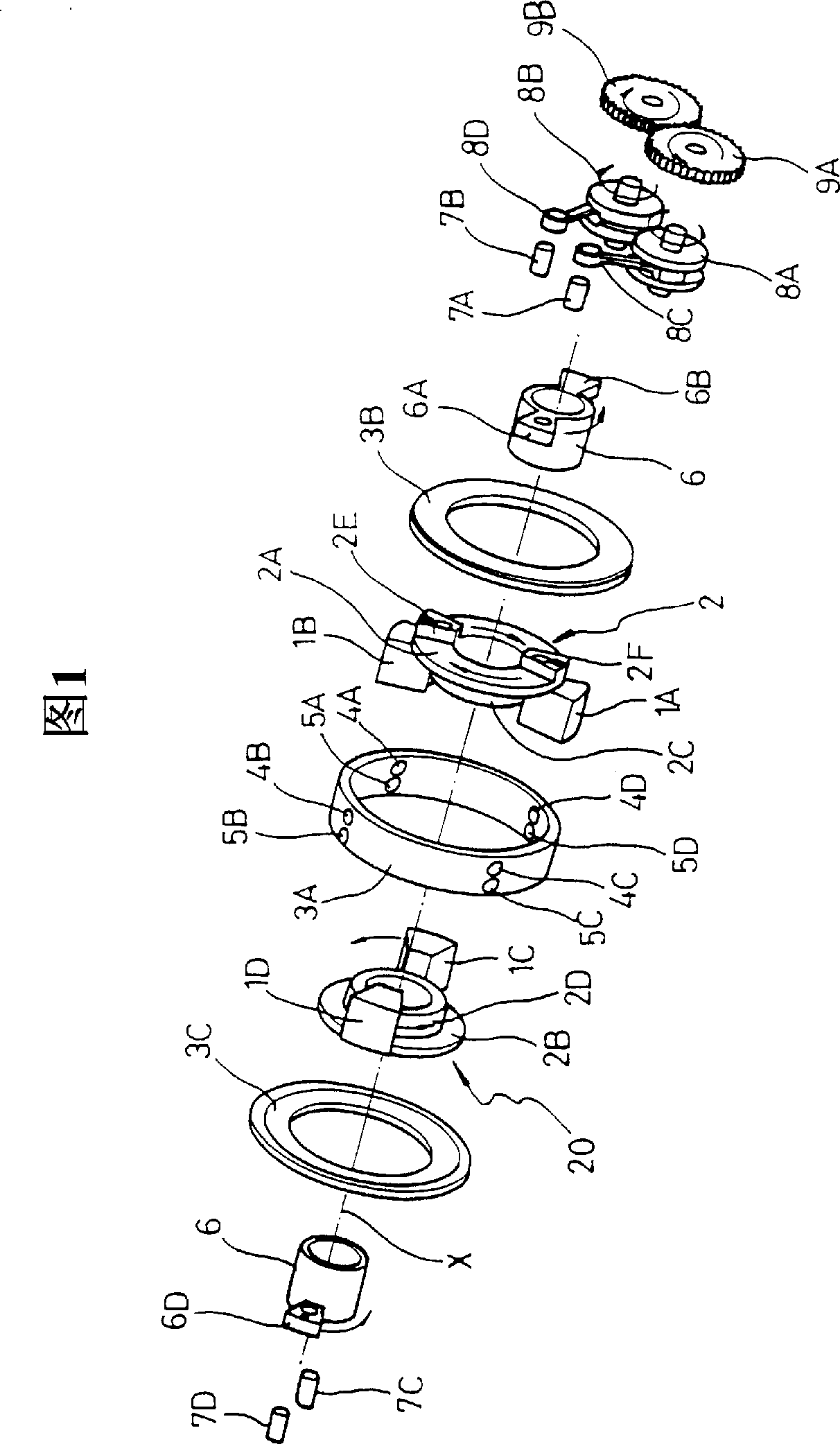
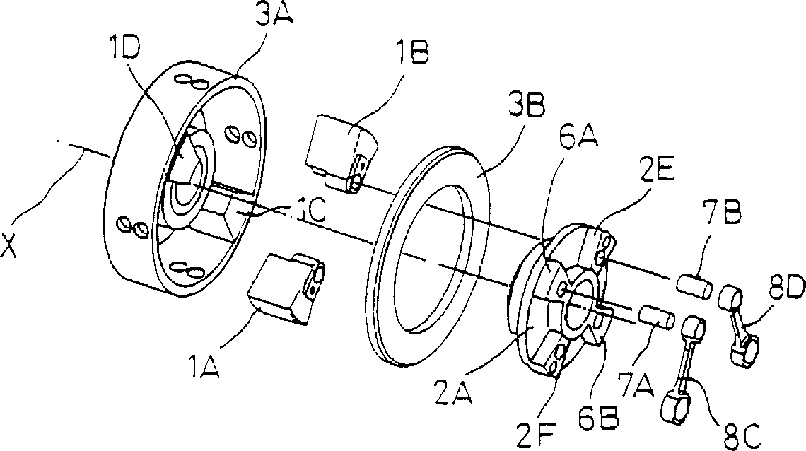
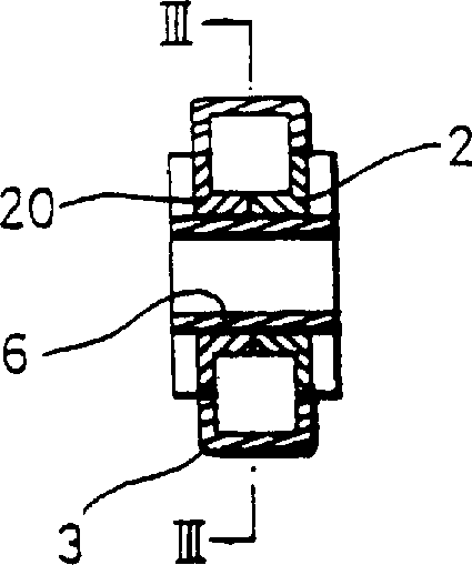
[0028] First please refer to Fig. 1 to Fig. 3, according to the reciprocating and rotating 4-cylinder piston device of the first embodiment of the present invention, its cylinder 3 is composed of an outer cylindrical part 3A, a left / right annular ring combined with the two ends of the outer cylindrical part 3A Plates 3C, 3B are formed.

[0029] At both ends of the cylinder 3, in the circumferential direction of the central axis X, annular plates 2A, 2B with the same shape as the inner diameter of the annular plates 3C, 3B are respectively provided; inside the annular plates 2A, 2B, there are respectively formed The inner cylindrical portions 2C, 2D of the inner surface of the cylinder 3, which are integrally formed with the annular plates 2A, 2B, extend toward the inside of the cylinder, and on the outer peripheral surfaces of the respective inner cylindrical portions 2C, 2D, A pair of pistons 1A, 1B and 1C, 1D having a height and a width in the outer circumferential direction...


PUM


Abstract

A reciprocating rotary piston system includes a cylinder having an annular and hollow interior; a plurality of pistons (1A to 1D) of which first and second parties are formed to be disposed alternately on the same inner circumference of the cylinder, the first and second parties of the pistons reciprocating along a given arc at the same speed and in the opposite direction with respect to each other; a plurality of intake valves (4A to 4D) mounted at each point of the cylinder where the two adjacent pistons meet for controlling flow of a fluid introduced thereinto from the outside; and a plurality of exhaust valves (5A to 5D) mounted at each point of the cylinder where the two adjacent pistons meet for controlling flow of a fluid forced out from the inside. The piston system is used for a hydraulic / pneumatic pump, a vacuum pump and an internal combustion engine.

Description

technical field [0001] The present invention relates to a reciprocating rotary piston device and a pressure pump and an internal combustion engine using the device, in particular to such a reciprocating rotary piston device and various internal combustion engines, hydraulic pumps, air pumps, vacuum pumps, etc. using the piston device etc., its structure is that many pairs of pistons are arranged alternately on the same circumference inside the cylinder, and the adjacent pistons rotate in opposite directions at the same speed, due to the resultant force generated by the movement of these pistons in the structure The vibrations they generate cancel each other out, so the vibration and noise, as well as the resulting wear and tear are reduced, thereby prolonging the life of the machine, realizing miniaturization, reducing its weight and improving its performance. Background technique [0002] Various internal combustion engines, hydraulic pumps or air pumps, vacuum pumps, etc.,...

Claims


Application Information

Patent Timeline
Patent Type & Authority Applications(China)
IPC IPC(8): F01C1/00F01C9/00F01L1/00F02B53/00F02B75/02F04C9/00F04C21/00
CPCF01C9/002F02B2075/027F01C1/00
Inventor 金昌钧金承钧
Owner 金昌钧
Why Eureka
Try Eureka