Ozone/hydrogen peroxide advanced film oxide reactors

A technology of hydrogen peroxide and advanced oxidation, which is applied in the direction of oxidized water/sewage treatment, etc., and can solve the problems of low reaction efficiency and consumption

Active Publication Date: 2007-01-24
ERDOS ANXINTAI ENVIRONMENTAL PROTECTION TECH
View PDF5 Cites 0 Cited by
  • Summary
  • Abstract
  • Description
  • Claims
  • Application Information

AI Technical Summary

Problems solved by technology

However, if too much hydrogen peroxide is added locally, the generated free radicals will react, and the remaining hydrogen peroxide can also react with free radicals as follows: In the previous single-point dosing, due to the concentration of hydrogen peroxide dosing, some hydroxyl radicals were consumed before participating in the reaction of oxidizing organic matter, and the reaction efficiency was very low.

Method used


Image

  • Ozone/hydrogen peroxide advanced film oxide reactors
  • Ozone/hydrogen peroxide advanced film oxide reactors
  • Ozone/hydrogen peroxide advanced film oxide reactors

Examples


specific Embodiment approach 1

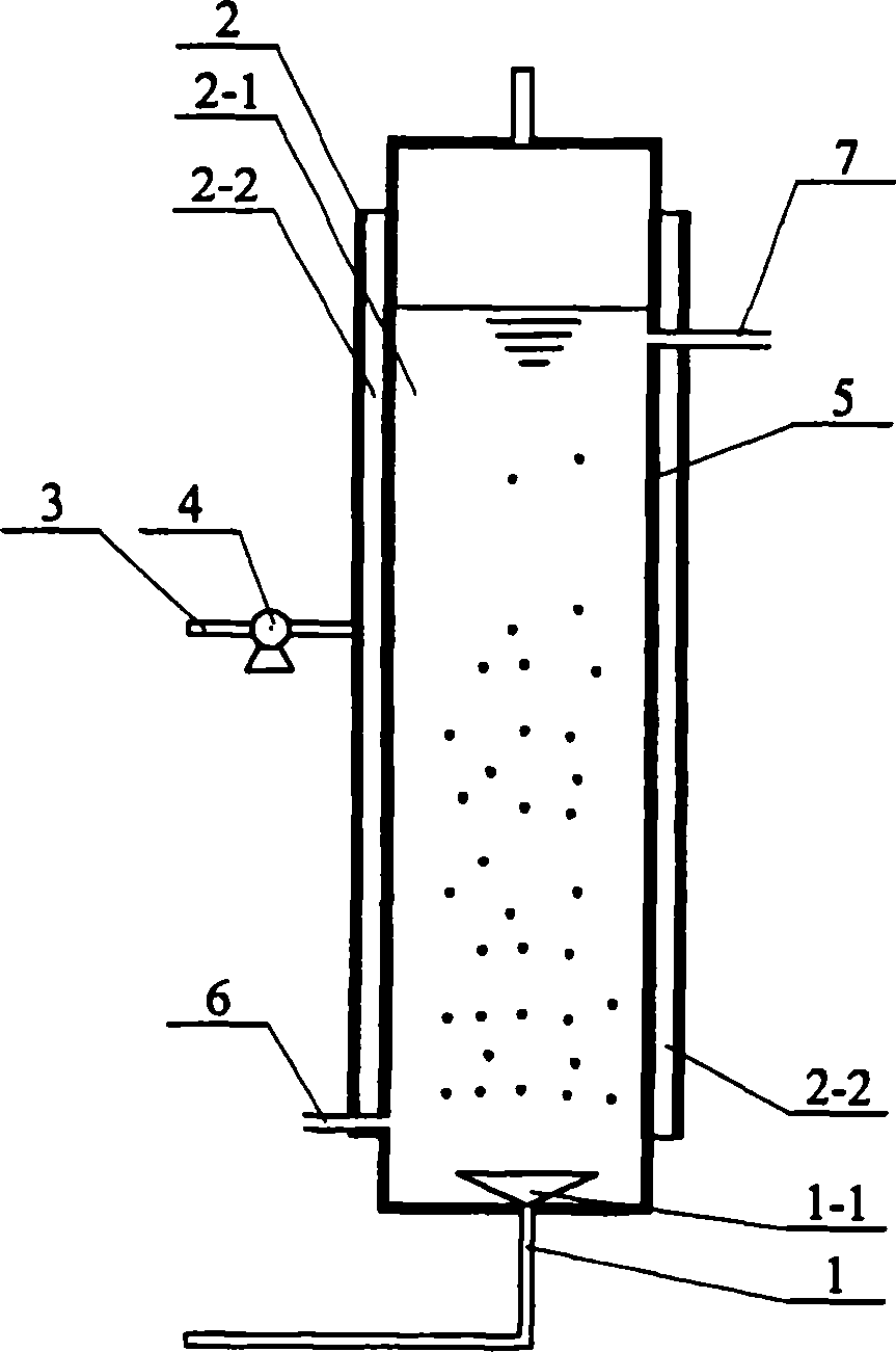
[0005] Specific implementation mode one: the following combination figure 1 This embodiment will be specifically described. This embodiment is composed of ozone exposure pipe 1, reaction vessel 2, water inlet pipe 6, water outlet pipe 7, catalyst inlet pipe 3, membrane body 5 and booster pump 4, and the membrane body 5 that can be permeated by hydrogen peroxide molecules will react The space in the container 2 is separated into a reaction chamber 2-1 and a hydrogen peroxide chamber 2-2, the inner end of the ozone exposure pipe 1 is connected to the bottom in the reaction chamber 2-1, and the inner side of the water inlet pipe 6 and the water outlet pipe 7 The ends communicate with the reaction chamber 2-1 respectively, the booster pump 4 is arranged in the catalyst inlet pipe 3, and the inner end of the catalyst inlet pipe 3 is connected to the hydrogen oxide chamber 2-2. An aeration head 1-1 is arranged on the inner end of the ozone exposure pipe 1 . The water inlet pipe 6 ...

specific Embodiment approach 2

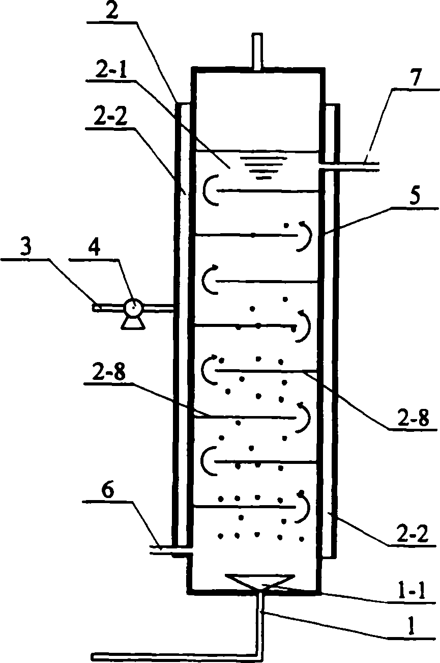
[0006] Specific implementation mode two: the following combination figure 2 This embodiment will be specifically described. The difference between this embodiment and Embodiment 1 is that several baffles 2-8 are fixed on the inner wall surface of the reaction chamber 2-1 from top to bottom, and the several baffles 2-8 are arranged staggeredly from top to bottom. On the surface of the inner wall of the reaction chamber 2-1, adjacent baffles 2-8 are respectively fixed on opposite surfaces of the inner wall of the reaction chamber 2-1. Such setting makes the water body zigzagging upwards to form turbulent flow, so that ozone and hydrogen peroxide can mix and contact more fully.

specific Embodiment approach 3

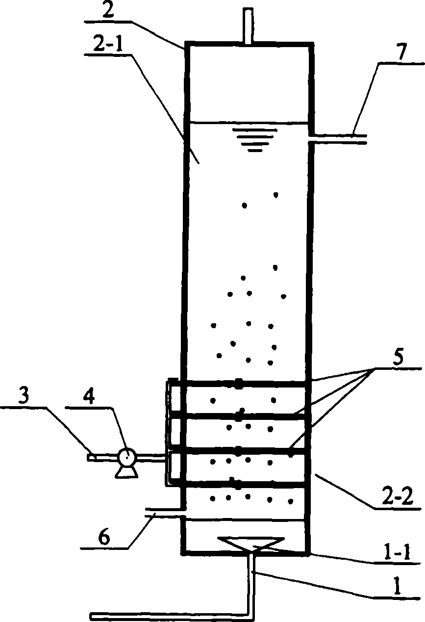
[0007] Specific implementation mode three: the following combination image 3 and Figure 4 This embodiment will be specifically described. The difference between this embodiment and Embodiment 1 is that the membrane body 5 uses several tubular membranes or several groups of hollow fiber modules, and all the tubular membranes or hollow fiber modules are horizontally arranged in the reaction vessel 2, and the tubular membranes or One end of the hollow fiber module is connected to the catalyst inlet pipe 3, and the other end of the tubular membrane or hollow fiber module is closed.


PUM


Abstract

A water-reacting reactor for catalyzing ozone organic matter process by hydrogen peroxide achieves higher organic matter removing rate. The ozone / hydrogen peroxide high-graded oxide membrane reactor consists of an ozone aerating tube1, a reactor2, a water inlet tube6, a water outlet tube7, a catalyst inlet tube3, a membrane5 and a pressurized pump4. The space of the reactor is separated with the reacting cavity2-1 and the hydrogen peroxide cavity2-2 by membrane with hydrogen peroxide molecular penetration, the internal side end of the water inlet tube6 and the water outlet tube7 is connected with the reacting cavity2-1, the internal end of the catalyst inlet tube3 is connected with the hydrogen peroxide cavity2-2. It can decrease residual account of hydrogen peroxide and pressure of follow-up treatment.

Description

Technical field: [0001] The invention relates to a water treatment reaction device for catalyzing the ozonation process of organic matter with hydrogen peroxide. Background technique: [0002] In recent years, with the rapid development of industry and agriculture and the continuous improvement of human material living standards, water pollution has become a common problem. A large number of toxic and harmful organic substances such as pesticides and chemical products are discharged into the water body, causing serious pollution of the water body. Usually these substances have high biological and chemical stability, and are difficult to be removed in conventional water treatment processes. At the same time, due to the continuous increase of the concentration of organic matter in the water body, the chlorine consumption and the amount of disinfection by-products in the disinfection process have increased significantly. The harmful organic substances discharged into the water...

Claims


Application Information

Patent Timeline
IPC IPC(8): C02F1/72
Inventor 马军王群
Owner ERDOS ANXINTAI ENVIRONMENTAL PROTECTION TECH
Why Eureka
Try Eureka