Interference type optical fiber gyroscope based on MZ interference principle

A fiber optic gyroscope, interferometric technology, applied in instruments, optical devices, measurement devices, etc., can solve the problems of low signal-to-noise ratio, low optical power utilization, interference, etc., and achieve high sensitivity, high cost performance, and stable performance. Effect

Inactive Publication Date: 2007-03-28
UNIV OF ELECTRONICS SCI & TECH OF CHINA
View PDF7 Cites 1 Cited by
  • Summary
  • Abstract
  • Description
  • Claims
  • Application Information

AI Technical Summary

Problems solved by technology

[0009] The purpose of the present invention is to overcome the disadvantages of low optical power utilization rate of the traditional interference fiber optic gyroscope, interference caused by the transmission of interference light and forward light in the same optical path, and low signal-to-noise ratio, and to provide an MZ interference-based The principle of interferometric fiber optic gyroscope, the gyroscope adopts the MZ interference principle which is different from the Sagnac interference principle, its forward transmission light path and interference light path are independent, there is no interference between them, and there is no multiple optical branching. power loss

Method used


Image

  • Interference type optical fiber gyroscope based on MZ interference principle
  • Interference type optical fiber gyroscope based on MZ interference principle
  • Interference type optical fiber gyroscope based on MZ interference principle

Examples


Embodiment Construction

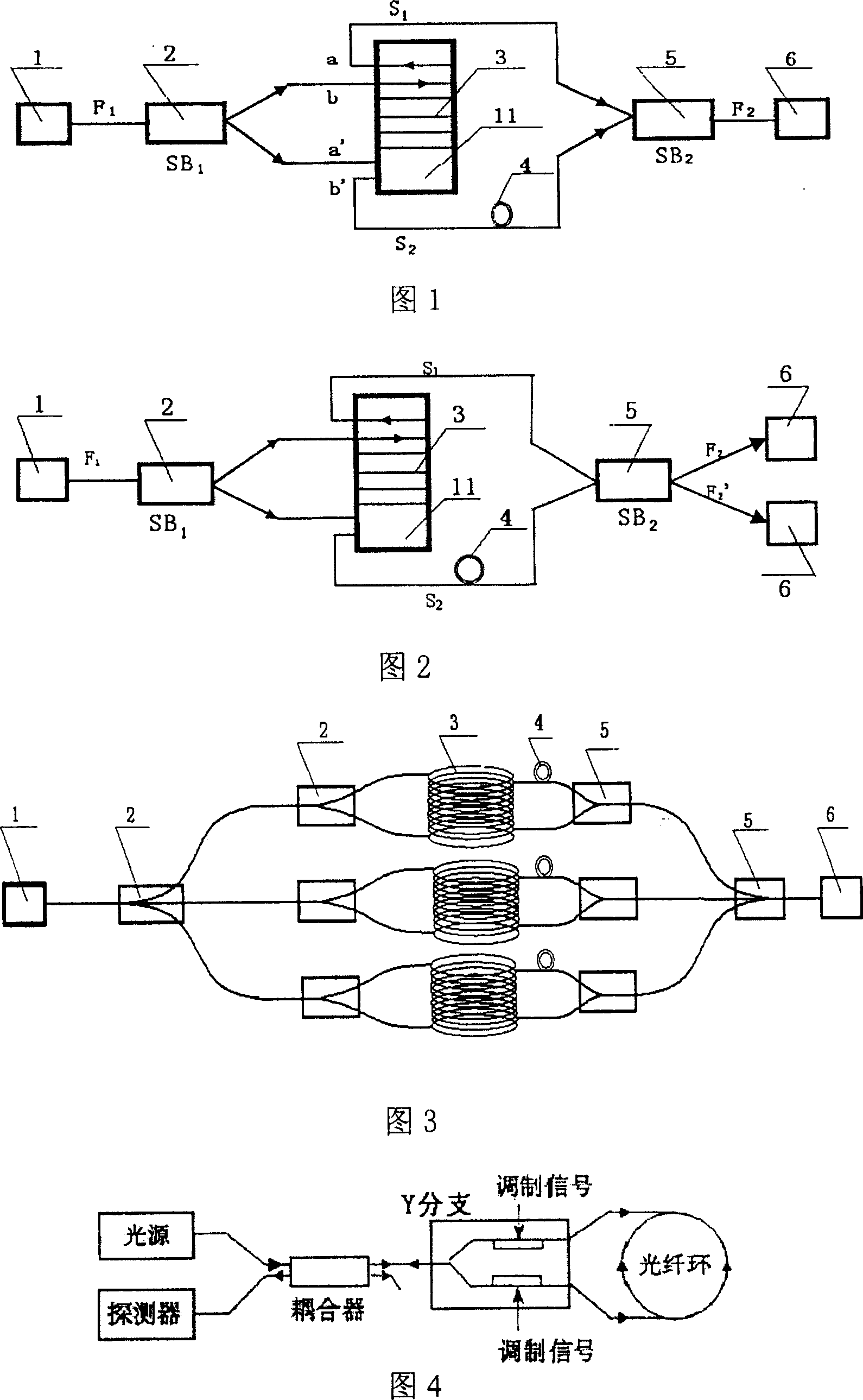
[0044] Referring to FIG. 1 , it is a schematic structural diagram of a single-axis MZ interferometric fiber optic gyroscope according to an embodiment of the present invention. The present invention adopts the principle of M-Z interference with two-arm symmetrical ring optical fiber (non-resonant type), which is completely different from the principle of Sagnac interference type fiber optic gyroscope and resonant type fiber optic gyroscope. Laser light with a wavelength of 0.8 μm to 1.6 μm emitted from the LD semiconductor laser enters the single-mode fiber F 1 After being 3db beam splitter 2SB 1 After splitting, the beams are sent to two optical fiber signal arms S with exactly the same length 1 In ports a, a' and S2 ports b, b', the two optical fiber signal arms are wound into optical fiber coils 3 with the same center of circle, the same diameter D, and the same winding method, and the optical signals are respectively transmitted from S 1 port a' of the arm and S 2 The p...


PUM


Abstract

The invention relates to an interference type optical fiber gyro based on principle of MZ interference, wherein the gyroscopic instrument comprises an illuminating source, a beam divider, an optical supervisory instrument, and an optical fiber sensor coil composed of two optical fiber arms of MZ interference, wherein the light from the light source is connected to the starting terminal and ending terminal of the two optical fiber arms on the optical fiber coils after the beam divider. The forward conduction optical path is separate from the intervened optical path, thus no interference is resulted.

Description

technical field [0001] The invention relates to a fiber optic gyroscope, in particular to an interferometric fiber optic gyroscope based on the principle of Mach-Zehnder interference. Background technique [0002] Fiber optic gyroscope is a new type of all-solid-state inertial instrument without mechanical rotor. It has broad application prospects in aerospace, aviation, navigation, vehicles, military and many civil fields, and has received extensive attention at home and abroad. The development of fiber optic gyroscopes has a history of more than 20 years. There are many related articles and works published, and many patents. After years of research, several fiber optic gyroscopes have been industrialized so far, and they have been used in military and civilian fields. get applied. From a technical point of view, the current fiber optic gyroscopes mainly include interferometric fiber optic gyroscopes using Sagnac interference effect and resonant fiber optic gyroscopes. Sag...

Claims


Application Information

Patent Timeline
Patent Type & Authority Patents(China)
IPC IPC(8): G01C19/58G01B9/02
Inventor 刘永智曾雪飞代志勇汤卫国彭增寿吴金谦张利勋
Owner UNIV OF ELECTRONICS SCI & TECH OF CHINA
Why Eureka
Try Eureka