
Novel vortex street flowmeter sensor

A vortex flowmeter and sensor technology, which is applied in the direction of volume/mass flow generated by mechanical effects, and through the detection of dynamic effects of fluid flow, etc., can solve problems such as easy aging, poor shock resistance, and high temperature difference

Inactive Publication Date: 2002-02-13
陈宝荣
View PDF0 Cites 3 Cited by
  • Summary
  • Abstract
  • Description
  • Claims
  • Application Information

AI Technical Summary

Problems solved by technology

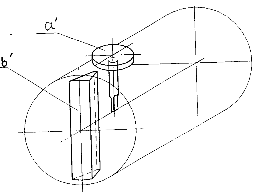
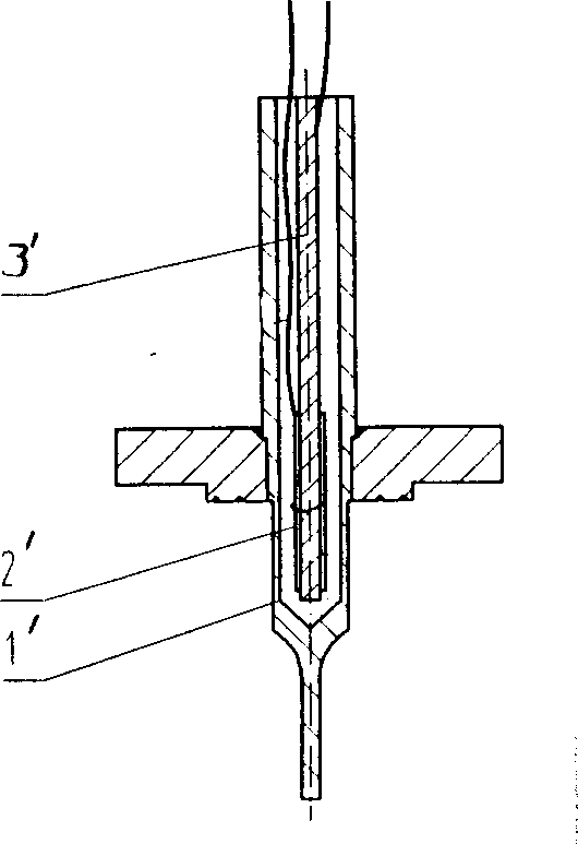
[0003] The current production of vortex flowmeter sensors can be roughly divided into two types: one is based on the signal detection element as the thickness of the bending vibration structure see figure 1 , the structure is that a pair of piezoelectric ceramic sheets 2 are pasted on the probe mandrel 3 and then inserted into the probe housing. The wiring method can be series or parallel connection, and then the housing is filled with fillers. The detection element a The cantilever is inserted into the wake behind the triangular column blocking column b. This structure has a short service life due to the high temperature difference of the filling material and the low operating temperature of the solid detection element. Also, because the detection element is packaged with filler material, it is easy to age. , the disadvantage of poor seismic performance
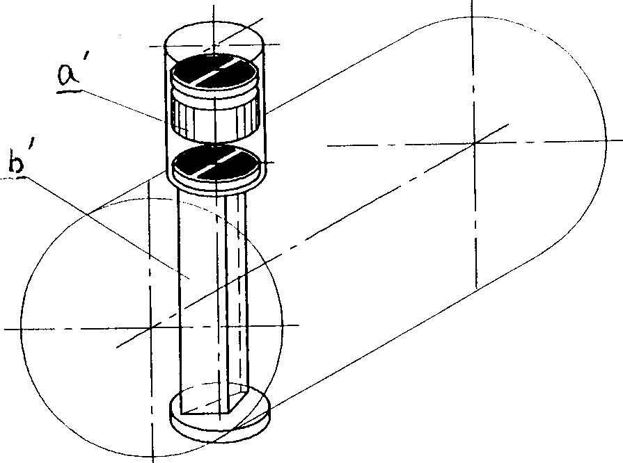
Another type of vortex sensor uses the thickness of the ceramic disc as the vibration mode. See image 3 , is to put two pairs of piezoelectric ceramic elements with opposite polarization directions into the shell of the signal detection element, and press them evenly with a pressure block. The detection element a is directly integrated with the triangular column retaining column b. Although this structure Good anti-interference performance, long service life, good high temperature resistance, but because the triangular prism is required to be able to generate strong vortex, but also to be able to detect vortex frequency, that is, the former requires that the triangular prism should be a fixed structure, while the latter requires that the triangular prism should be able to produce swings , so that the control of its processing size and precision is very complicated, so the processing requirements are high

Method used


Image

  • Novel vortex street flowmeter sensor
  • Novel vortex street flowmeter sensor
  • Novel vortex street flowmeter sensor

Examples


Embodiment Construction

[0022] The figure is the detection element in the prior art is a structure diagram of thickness bending vibration, image 3 It is a schematic diagram of the structure of the wafer thickness vibration type used in the prior art.

[0023] Figure 4 is a structural design diagram of the present invention, the signal detection element a is located behind the triangular block cylinder b, please refer to Figure 7 --- Figure 14 , which is a cross-sectional structure diagram of several signal detection elements in the present invention, Figure 7 The bottom of the middle probe shell 1 is a plane structure 12, the probe 1 is designed as a round rod, and there is an annular groove 13 on the probe shell 1 to ensure better work of the detection element, and the inner cavity 10 of the probe shell is directly put into the press The electric ceramic garden piece 2, so that one end of the piezoelectric ceramic garden piece 2 is directly attached to the bottom of the inner cavity 10 of the ...


PUM


Abstract

The novel vortex street flowmeter sensor has piezoelectric ceramic wafer vibration membrane structure as signal detecting element, and has piezoelectric ceramic wafer inside the casing cavity of probe. One end of the piezoelectric ceramic wafer is adhered directly to the bottom of the casing and the other end to the connection board. The piezoelectric ceramic wafer is pressed by one holddown block with insulating material in between. The wires are led out from the holddown block and the connection board. The probe is one rod structure, has planar top and the casing of the probe has one ring groove. The present invention has the advantages of simple production, high sensitivity, high vibration resistance, high precision repetition, etc.

Description

1. Technical field [0001] The invention relates to a vortex flowmeter, in particular to a vortex flowmeter sensor [0002] The detection element used on the device. 2. Background technology [0003] The current production of vortex flowmeter sensors can be roughly divided into two types: one is based on the signal detection element as the thickness of the bending vibration structure see figure 1 , the structure is that a pair of piezoelectric ceramic sheets 2 are pasted on the probe mandrel 3 and then inserted into the probe housing. The wiring method can be series or parallel connection, and then the housing is filled with fillers. The detection element a The cantilever is inserted into the wake behind the triangular column blocking column b. This structure has a short service life due to the high temperature difference of the filling material and the low operating temperature of the solid detection element. Also, because the detection element is packaged with filler mater...

Claims


Application Information

Patent Timeline
IPC IPC(8): G01F1/32
Inventor 陈宝荣
Owner 陈宝荣
Learn More