Frequency generator circuit

A circuit and frequency adjustment technology, applied in power oscillators, electrical components, automatic control of power, etc.

Inactive Publication Date: 2002-03-20
MARCONI COMM LTD
View PDF1 Cites 1 Cited by
  • Summary
  • Abstract
  • Description
  • Claims
  • Application Information

AI Technical Summary

Problems solved by technology

[0005] Although this known circuit can for example provide a frequency division function with very low phase noise, this involves a lot of expense considering that it must also be incorporated with some form of additional frequency adjustment means

Method used


Image

  • Frequency generator circuit
  • Frequency generator circuit
  • Frequency generator circuit

Examples


no. 1 example

[0010] Figure 3 shows a first embodiment of an oscillator circuit according to the invention;

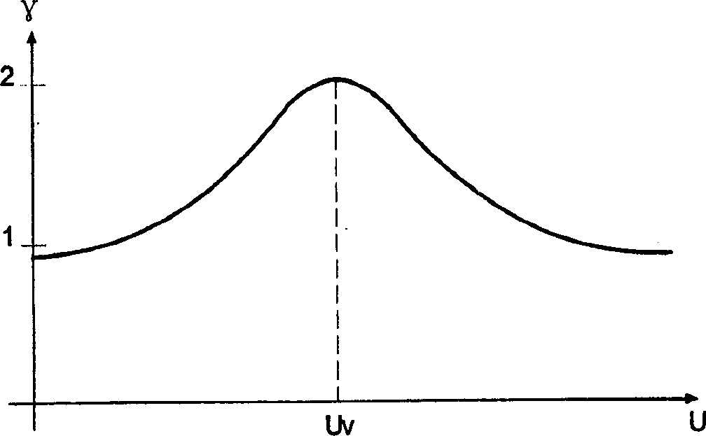
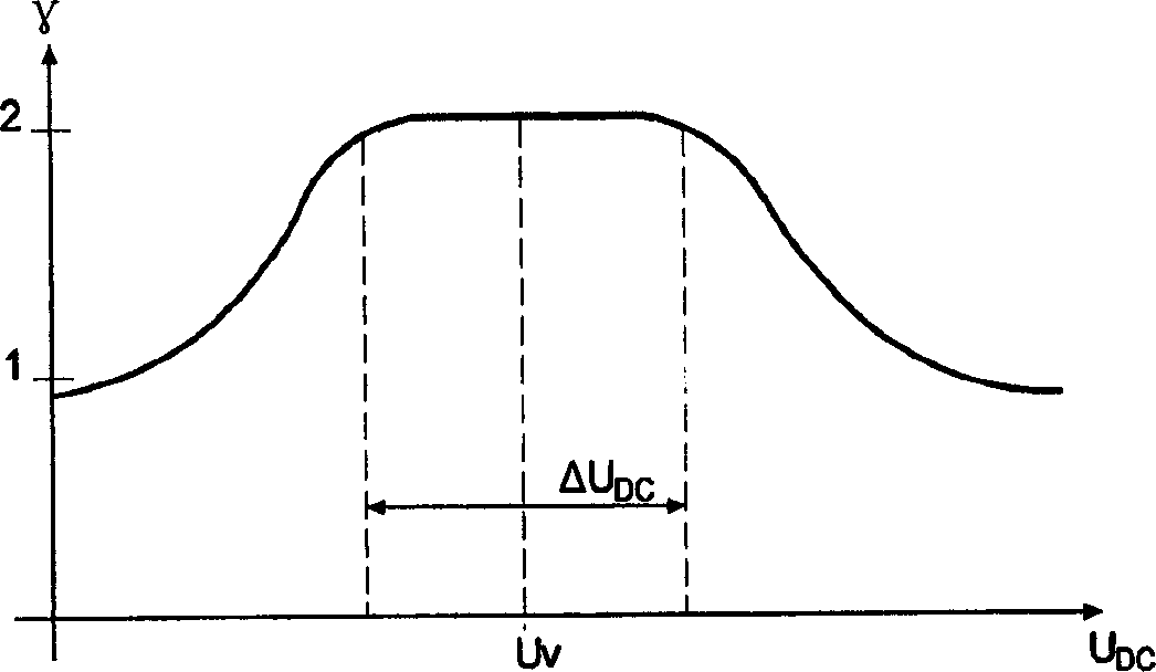
[0011] Figure 4 It is a curve graph between the gamma value and the bias voltage of a varactor diode suitable for application in the present invention;

[0012] Figures 5, 6, 7 and 8 show first, second, third and fourth implementations of a second embodiment of an oscillator circuit according to the invention.

[0013] With reference to Fig. 3, it shows the first embodiment of the present invention, wherein, there is microstrip 21 on one side of a dielectric resonator 20 that is made of ceramic disc, and an oscillator device 22 is arranged at one end of this microstrip 21, For example, it is a FET tube or a monolithic integrated oscillator circuit shown, the other end of the microstrip 21 is grounded through a matching impedance 23, and there is a second microstrip 24 on the other side of the dielectric resonator 20, its One end is terminated to ground by a varactor diode 25 , th...


PUM


Abstract

A frequency-generator circuit employs the same circuit element (preferably a varactor) to perform the functions of parametric frequency-divider and frequency-adjustment element for an oscillator used to pump the parametric frequency-divider.The varactor preferably has a flat gamma-characteristic (gamma preferably > 2) over a required bias-voltage adjustment range corresponding to the required frequency-adjustment range.

Description

[0001] The technical field of the present invention [0002] The present invention relates to frequency generator circuits incorporating a parametric frequency divider. Background of the invention [0003] Oscillators used in phase-locked loops (PLLs) often require a divider section to reduce the input frequency to a value that can be handled by the phase detector. An example of a frequency divider operating on the parametric principle is described in German Patent DE 19529529, published October 31, 1996, by Robert Bosch (Ag) and shown in FIG. 1 . In Fig. 1, the key element is the varactor diode 10, which acts as a nonlinear reactance. Upstream of the diode 10 is an input filter 11, which is a high-pass filter tuned to the frequency of the input signal E, which in turn acts as an impedance converter to make the line impedance at the input of the circuit equal to the low input of the diode 10 impedance matching. There is an output filter 12 downstream of the diode 10, which ...

Claims


Application Information

Patent Timeline
IPC IPC(8): H03B5/12H03B19/05
CPCH03B5/1203H03B5/1876H03B19/05H03B5/1228H03B5/1243H03B25/00
Inventor M·沙尔纳U·穆勒W·康拉斯
Owner MARCONI COMM LTD
Why Eureka
Try Eureka