Continuous firing furnace and its use method

A technology for firing furnaces and sintering materials, applied in furnaces, furnace cooling, furnace types, etc., can solve the problems of equipment cost, operation cost increase, thermal efficiency reduction, etc., to achieve the effect of compensating for heat loss and increasing effective space

Inactive Publication Date: 2002-05-01
IHI CORP
View PDF0 Cites 21 Cited by
  • Summary
  • Abstract
  • Description
  • Claims
  • Application Information

AI Technical Summary

Problems solved by technology

However, fixing the upper and lower heat income and expanding the furnace shape beyond the required furnace shape will result in a decrease in thermal efficiency and increase in equipment and operating costs.

Method used


Image

  • Continuous firing furnace and its use method
  • Continuous firing furnace and its use method
  • Continuous firing furnace and its use method

Examples


Embodiment Construction

[0066] The continuous firing furnace of the present invention is preferably used when the sintering temperature is above 1600°C and below 2500°C, and its structure is described in detail below.

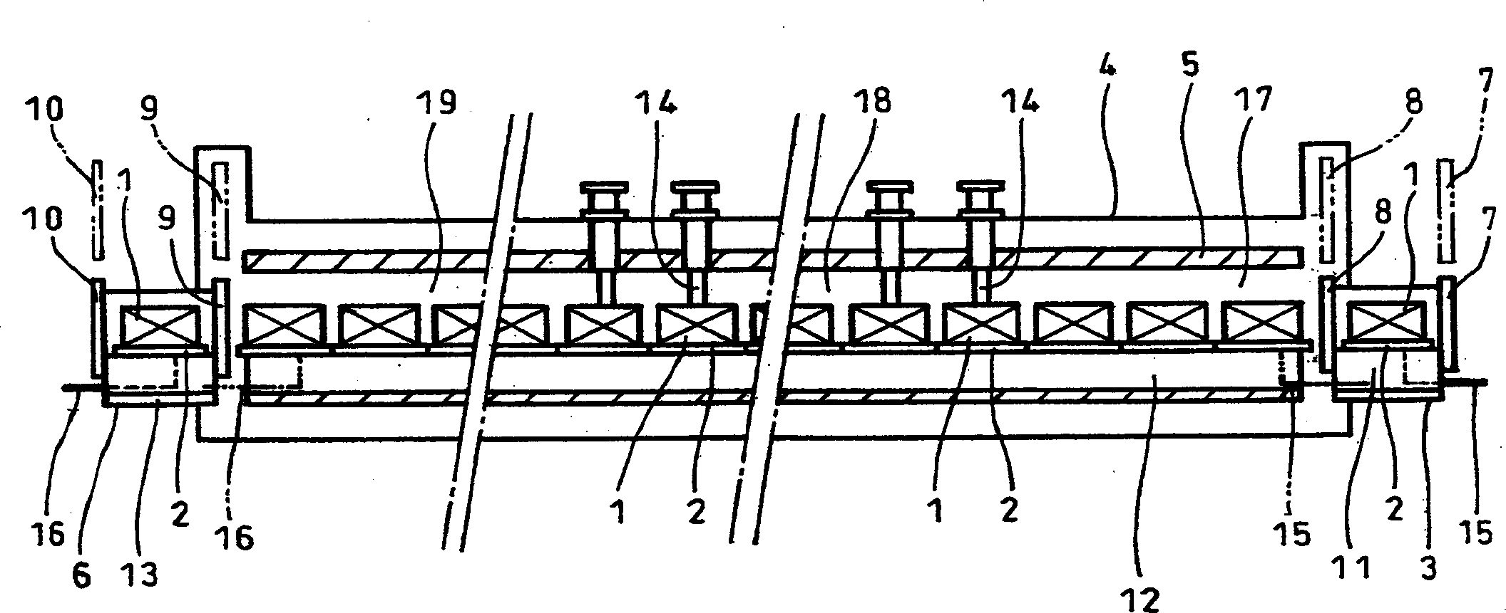
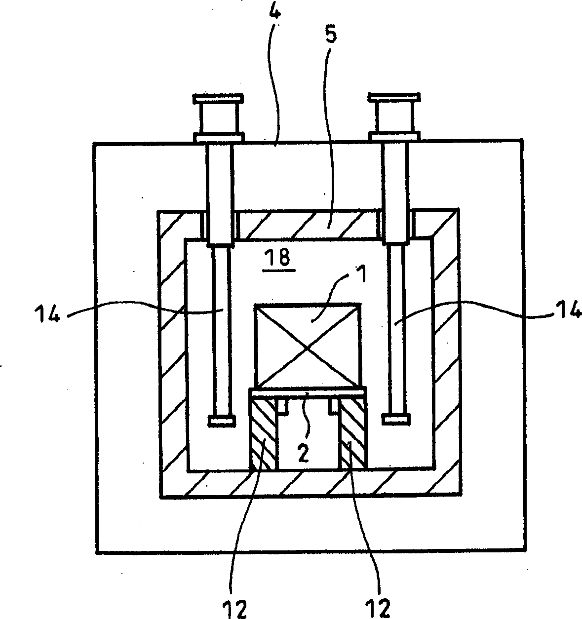
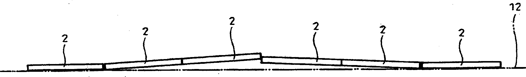
[0067] Figure 4-Figure 9 It is a figure showing embodiment 1 of the continuous firing furnace of the present invention, and is marked with and figure 1 and figure 2 Parts with the same symbols represent the same thing.

[0068] The continuous sintering furnace comprises: an input side degassing chamber 23 through which a pallet 22 of materials to be sintered 1 can pass; a chamber 24 connected to the input side degassing chamber 23; The firing furnace main body 25 that a plurality of trays 22 that are arranged in a row are sent into successively from input side degassing chamber 23; Air chamber 26; a plurality of free rollers pivotally supported in contact with the lower surface of the tray 22 on substantially the entire length of the firing furnace main body 25 and the downstream...


PUM


Abstract

A continuous sintering furnace has an entrance-side deaerating chamber through which trays each with an material to be sintered being mounted thereon may pass, preheating, heating and cooling zones into which the trays are sequentially fed from the deaerating chamber, an exit-side deaerating chamber through which the trays having passed through the cooling zone may pass, a pusher for pushing the tray from the deaerating chamber to the preheating zone, a puller for pulling the tray from the cooling zone to the deaerating chamber, an intermediate puller for pulling the tray from the heating zone to the cooling zone, a vertically movable door between the deaerating chamber and the preheating zone, a vertically movable intermediate door adjacent to the door and arranged at an upstream end of the preheating zone in the direction of transportation of the trays, a vertically movable intermediate door between the heating and cooling zones and a vertically movable door between the cooling zone and the deaerating chamber. With the door being at a lowered position thereof for closing, heat input is suppressed to the cooling zone. Movement of the trays in the cooling zone is effected by the intermediate puller so as to decrease the number of trays needing to be pushed by the pusher.

Description

technical field [0001] The continuous sintering furnace of the present invention is a sintering furnace for the purpose of continuously sintering a material to be sintered so that it becomes ceramics. The main processed material is alumina (Al 2 o 3 ), silicon carbide (SiO), boron nitride (BN) and other ceramic materials other than carbide, nitride and oxide, the processing temperature is above 1600°C. At such a high temperature, the above-mentioned sintering furnace is continuously sintered. Its structure, material, and mechanism are important factors, especially the material. Because the high-temperature-resistant material is mainly graphite, the physical properties, structure, and mechanism are greatly restricted. Background technique [0002] figure 1 , figure 2 It is an example of the existing continuous sintering furnace, and the continuous sintering furnace includes: the input side degassing chamber 3 through which the tray 2 placed with the material 1 to be sin...

Claims


Application Information

Patent Timeline
Patent Type & Authority Applications(China)
IPC IPC(8): F27B9/14F27B9/02F27B9/04F27B9/06F27B9/12F27B9/24F27B9/36F27B21/00F27D3/02F27D9/00F27D21/00
CPCF27B9/028F27B2009/2492F27B9/047F27B9/12F27D2021/0092F27B2009/3638F27D3/028F27B21/00F27B9/063F27D2009/0013Y02P40/60F27B9/14
Inventor 森和美井浦透石本哲也胜俣和彦町田洋
Owner IHI CORP
Why Eureka
Try Eureka