Method for eliminating residual gas in field emission display and gas released by material

A technology of residual gas and display devices, which is applied in the manufacture of electrical components, discharge tubes/lamps, and cold cathodes, and can solve problems such as weakening of the tip field strength, reduction of emission current, and shortening of the life of field emission displays.

Inactive Publication Date: 2002-06-12
SOUTHEAST UNIV
View PDF0 Cites 5 Cited by
  • Summary
  • Abstract
  • Description
  • Claims
  • Application Information

AI Technical Summary

Problems solved by technology

The bombardment of ions will enter the surface of the micro-tip material, forming a high-resistance layer on the surface of the micro-tip, and at the same time, the bombardment of ions will damage the tip of the micro-tip, which will weaken the field strength of the tip, cause a decrease in the emission current, and finally make the field emission The life of the display is shortened

Method used


Image

  • Method for eliminating residual gas in field emission display and gas released by material
  • Method for eliminating residual gas in field emission display and gas released by material

Examples


Embodiment Construction

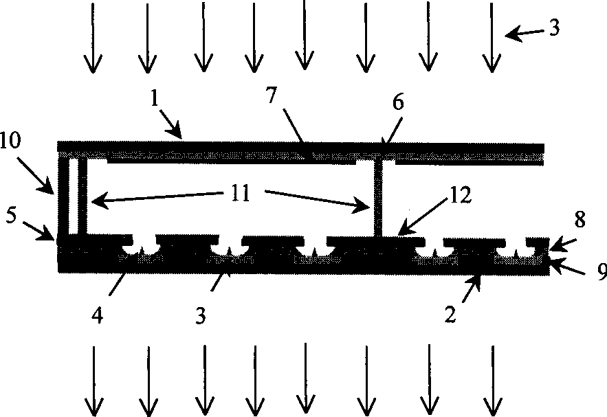
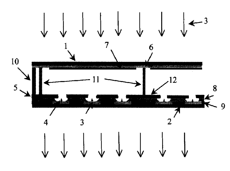
[0017] The field emission display includes a front glass substrate 1 as the effective display working surface of the display device and a rear glass substrate 2 parallel to the front glass substrate; multiple cathode electrodes 3 parallel to each other are arranged on the rear glass substrate and located at The micro-tip electron emitter 4 on which is kept electrically connected; the micro-tip electron emitter starts to emit electrons when its electric field reaches a certain intensity under the control of its corresponding gate electrode 5, and the emission current increases with the increase of the electric field intensity; The emitted electrons are accelerated toward the anode under the action of the transparent conductive anode 6 on the front substrate, and the anode and the cathode are arranged orthogonally; and after passing through a vacuum space, they bombard the phosphor powder 7 on the front substrate to make the phosphor emit light. Can be seen through the transparen...


PUM


Abstract

A method for elimnating the residual gas in field emission display and the gas release from material features that when the field emission display is treated by ageing step, a magnetic ion trap in the form of magnetic field is arranged outside the said display while positive voltage higher than that of cathode is applied to the gate electrode to emit electrons, so eliminating the said gas. In the ageing process of the field emission display, the ageing may be for the entire display at the same time, or for several parts of the display separately.

Description

1. Technical field: [0001] The invention relates to a method for eliminating residual gas in a field emission device, in particular to a process method for eliminating residual gas and material outgassing in a field emission display device by using a magnetic ion trap. 2. Background technology: [0002] Flat-panel display devices are currently a hot spot in the development of displays. At present, there are more flat-panel displays that have been studied, such as liquid crystal displays, plasma displays, and field emission displays. Because liquid crystal displays are passively emitting light, the brightness is low, and at the same time, there are small viewing angles and slow response speeds. problems; the size of the plasma display is large, but there are certain difficulties in luminous efficiency and high-resolution display; and the field emission display is a cold cathode emission, active light-emitting flat panel display device, which has high luminous brightness, low p...

Claims


Application Information

Patent Timeline
Patent Type & Authority Applications(China)
IPC IPC(8): H01J9/38
Inventor 张晓兵雷威
Owner SOUTHEAST UNIV
Why Eureka
Try Eureka