Check patentability & draft patents in minutes with Patsnap Eureka AI!

Magnetic random access memory

A technology of random access memory and magnetoresistive devices, which is applied in the direction of static memory, digital memory information, information storage, etc., can solve the problem of narrow width, insufficient reduction of wiring current density, large storage capacity, high-capacity wiring reliability writing input errors etc.

Inactive Publication Date: 2002-07-31
KK TOSHIBA
View PDF0 Cites 3 Cited by
  • Summary
  • Abstract
  • Description
  • Claims
  • Application Information

AI Technical Summary

Problems solved by technology

[0027] As described above, in order to prevent the occurrence of electron migration and improve the reliability of the wiring, for example, measures to thicken the wiring have been considered, but this measure is not sufficient for reducing the current density of the wiring. To prevent write errors in unselected cells, the thickness of the wiring must be formed as thin as possible, so that the intensity distribution of the magnetic field generated by the current flowing on the wiring becomes a steep distribution with as narrow a width as possible.
[0028] That is, in the conventional MRAM, it is impossible to realize the increase in storage capacity by miniaturization of the memory cell, the improvement of the reliability of the wiring, and the prevention of writing errors at the same time.

Method used


Image

  • Magnetic random access memory
  • Magnetic random access memory
  • Magnetic random access memory

Examples


Embodiment 1

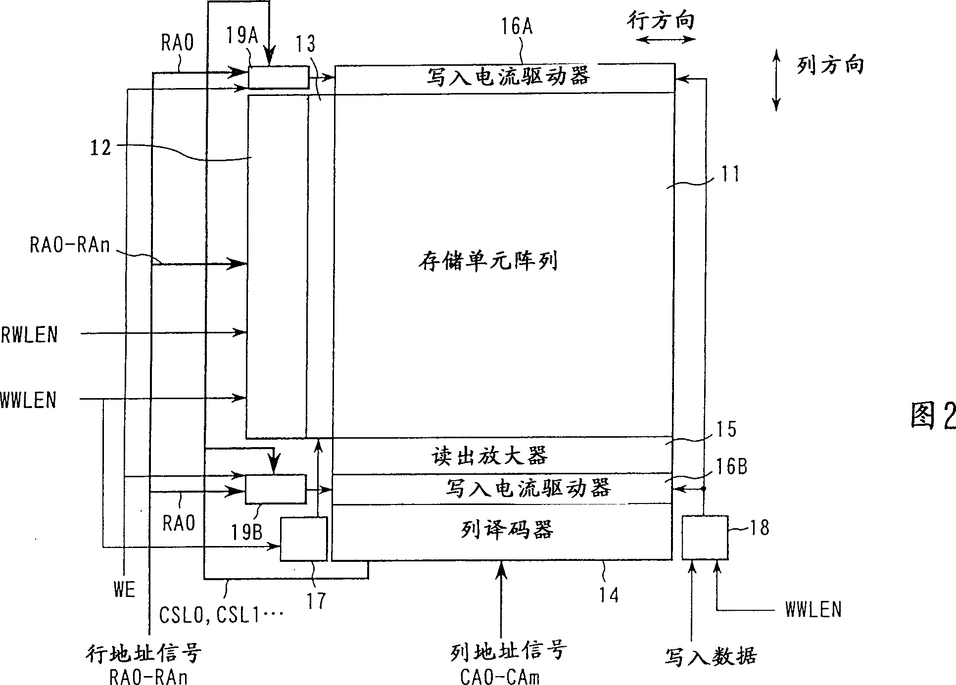
[0045] FIG. 2 shows the main part of the magnetic random access memory as Embodiment 1 of the present invention.

[0046] At the end of the memory cell array 11 in the row direction, a row decoder 12 is arranged. Row address signals RA0-RAn are input to row decoder 12 . Row decoder 12 enters an active state when write word line enable signal WWLEN or read word line enable signal RWLEN becomes enabled.

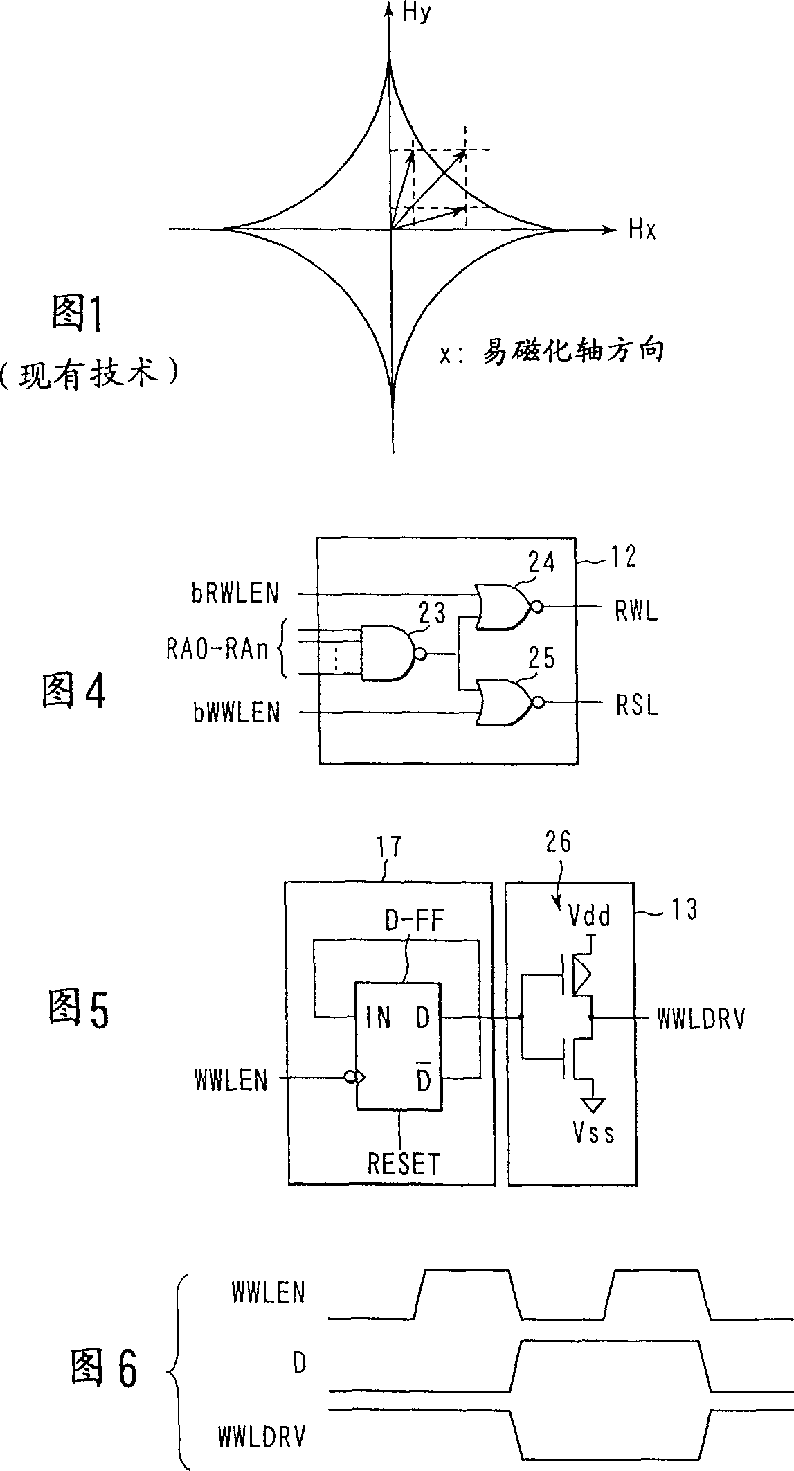
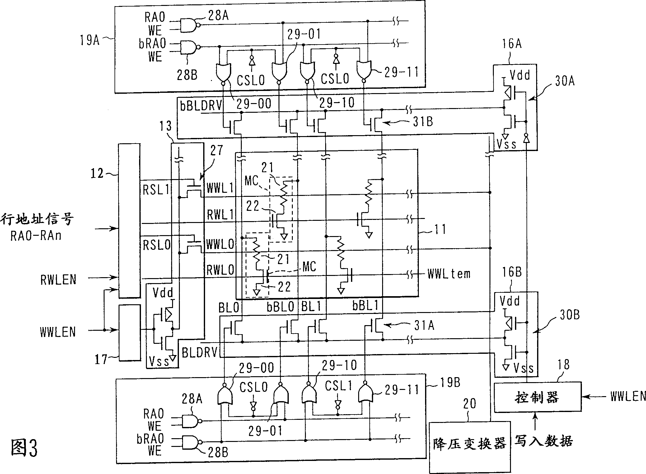
[0047] At the time of writing, row decoder 12 selects a write word line (row) WWL of memory cell array 11 based on row address signals RA0-RAn. The write word line WWL is used to make the magnetization directions of the two magnetic layers of the memory cell parallel or antiparallel together with the bit line BL to be described later. The WWL driver 13 functions to drive the selected write word line WWL.

[0048] The controller 17 enters the active state when the write word line enable signal WWLEN is in the enabled state. The controller 17 can be constituted by, for exampl...

Embodiment 2

[0109]Magnetic random access memory (MRAM) can perform random writing to any bit in the memory cell array. Here, as a method for increasing the writing bandwidth, for example, a method of fixing a row address and then writing to a memory cell located at the intersection of a row specified by the row address and a plurality of columns is known.

[0110] In MRAM, it is not preferable to simultaneously perform a write operation on all of a plurality of columns in order to increase a write current, since insufficient peak current supply and adverse effects such as radiation of electromagnetic waves may occur.

[0111] In this case, for example, the column selection signal CSLi for selecting a column is sequentially input with a time shift, and the data writing to the memory cell is performed one column at a time, without writing to all of the plurality of columns at the same time. into action.

[0112] Here, as can be seen from the star-shaped curve in FIG. 10 , when the magnetiz...


PUM


Abstract

In an MRAM, a current with high current density flows in a line in write operation. When write operation is to be performed with respect to a memory cell existing at the intersection of a write word line and a bit line, a current flows in the write word line from a WWL driver to a voltage down converter. Thereafter, a current flows in the write word line in a direction opposite to the direction of the current flowing in the write operation, i.e., from the voltage down converter to the WWL driver. The same applies to a bit line. For example, after write operation, a current flows in the bit line in a direction opposite to the direction of a current flowing in the write operation.

Description

technical field [0001] The present invention relates to a magnetic random access memory, and more particularly to a method for improving the reliability of a circuit in which a large current flows during writing. Background technique [0002] In recent years, as the phenomenon that the Magnetic Tunnel Junction (MTJ) has a large magnetoresistance ratio (Magneto-Resistive (MR) Ratio) at room temperature has been discovered by researchers, the application of tunneling magnetoresistance effect (Tunneling Magneto- Resistive (TMR)) MRAM realization, began to become a reality. [0003] Even before applying the TMR effect to the MRAM, people have already known the MRAM using the giant magnetoresistance effect (Giant Magneto-Resistive (GMR)). However, the MR ratio of MRAM to which the GMR effect is applied starts from a few percent and is about 10% at most. In addition, in the MRAM using the GMR effect, since a current flows in a low-resistance metal thin film, there is a problem t...

Claims


Application Information

Patent Timeline
IPC IPC(8): G11C11/14G11C11/15H01L21/8246H01L27/105H01L43/08
CPCG11C11/15G11C11/1693
Inventor 伊藤洋
Owner KK TOSHIBA
Features
  • R&D
  • Intellectual Property
  • Life Sciences
  • Materials
  • Tech Scout
  • Unparalleled Data Quality
  • Higher Quality Content
  • 60% Fewer Hallucinations
Learn More