Photovoltaic electric generation system automatically tracking sun

A photovoltaic power generation system and automatic tracking technology, which is applied in the field of solar energy utilization, can solve the problems of low cost performance, poor wind resistance, and low tracking accuracy, achieve reliable and high-precision tracking, enhance wind resistance, and improve performance and price than the effect

Inactive Publication Date: 2002-09-18
NANJING CHUNHUI SCI & TECH IND
View PDF2 Cites 73 Cited by
  • Summary
  • Abstract
  • Description
  • Claims
  • Application Information

AI Technical Summary

Problems solved by technology

According to the applicant's understanding, although the above-mentioned existing technologies have certain application value, they ...

Method used


Image

  • Photovoltaic electric generation system automatically tracking sun
  • Photovoltaic electric generation system automatically tracking sun
  • Photovoltaic electric generation system automatically tracking sun

Examples


Embodiment 1

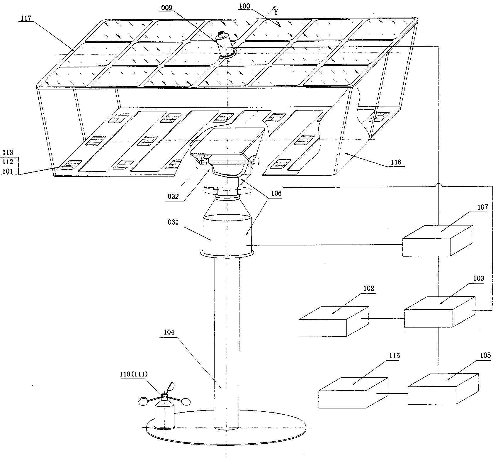
[0026] The system structure of Embodiment 1 of the present invention is as follows figure 1 As shown, the photovoltaic power generation system that automatically tracks the sun is composed of a condenser lens array 100, a solar cell array 101 and its mounting frame 117, a storage battery 102, a charge and discharge controller 103, an electrical appliance 115, a support 104, an inverter 105, and a drive The solar cell array tracks and aligns the mechanical transmission mechanism 106 of the sun, the tracking control circuit 107 that controls the mechanical transmission mechanism, the sunlight orientation sensor 009 that transmits signals to the tracking control circuit, and the radiator 109 (see Figure 6 ), a dust cover 116 and a windproof reset control device 110 are composed. Both the solar battery array 101 and the condenser lens array 100 are fixed on the mounting frame 117 . The mechanical transmission mechanism 106 is composed of an azimuth (east-west direction) drive me...

Embodiment 2

[0035] The basic structure and working principle of this embodiment are the same as those of the first embodiment, and the main difference lies in the altitude angle driving mechanism and the windproof reset control device.

[0036] Such as Figure 7 As shown, the mounting frame 117 is connected with the elevation angle driving mechanism 032 through the bearing 035, and the bearing 035 divides the mounting frame 117 into two parts 118 and 119 with different areas and weights, wherein the area and weight of 118 are larger than those of 119 . The altitude angle driving mechanism 032 includes an output shaft 036, a reel 037, a steel cable 038 and a fixed pulley 039, the reel 037 is fixedly connected with the output shaft 036, the fixed pulley 039 shaft is fixedly connected with the altitude angle drive 032, and the steel cable 038 It is wound on the reel 037 and connected to the installation frame 117 through the windproof reset control device 110 and the fixed pulley 039.

[0...

Embodiment 3

[0039] This example Figure 9 As shown, the structure of Embodiment 1 is also basically the same, and its difference has two points:

[0040] One is to use ordinary solar cell components instead of concentrating lenses and concentrating solar cells, such as Figure 9 shown. In addition, a layer of toughened protective glass 114 is covered on the surface of the solar cell array.

[0041] The second is that the optical signal receiver of the sunlight orientation sensor uses a photosensitive element instead of an optical fiber. Such as Figure 10 As shown, both the fine-tuning optical signal receiver and the coarse-tuning optical signal detector are composed of photovoltaic cells with better parameter symmetry performance.


PUM


Abstract

Photoelectric power generation system being able to follow sun autoamtically belongs to technical area of solar utilization. The system mainly composed of array of solar battery aid its mounting rack, mechanical transmission mechanism, tracking control circuit, sensor for sunlight orientation and resetting control equipment of wine proofing. The sensor for sunlight orientation includes condensinglens, sunlight signal receiver of fine and coarse adjustment. The sunlight signal receiver of fine adjustment includes light-sensitive surfaces in 4 orientations located on end face of base seat. Thesunlight signal receiver of coarse adjustment includes light-sensitive surfaces in 4 orientations located on perisporium of case. The condensing lens is fixed on top end of the case.

Description

technical field [0001] The invention relates to a solar photovoltaic power generation system, in particular to a photovoltaic power generation system that automatically tracks the sun, and belongs to the technical field of solar energy utilization. Background technique [0002] Solar energy is a clean and pollution-free renewable energy, inexhaustible and inexhaustible. Making full use of solar energy can not only alleviate the energy crisis, but also reduce the pollution caused by conventional energy sources, and protect the ecological environment on which human beings depend. Therefore, the development and utilization of solar energy has become an important strategic decision for sustainable development in all countries in the world. Among the many solar energy utilization technologies, solar photovoltaic power generation technology realizes the direct conversion of solar energy into electric energy, which is the most convenient way of utilization. It has the advantages of...

Claims


Application Information

Patent Timeline
IPC IPC(8): G01S3/78G05D3/00H02S20/32H02S40/22
CPCY02E10/52
Inventor 张耀明孙利国张振远张文进刘晓晖徐明泉陈修福陈士洁
Owner NANJING CHUNHUI SCI & TECH IND
Why Eureka
Try Eureka