Mud concentrated dehydration treatment equipment

A sludge concentration and treatment device technology, which is applied in the direction of dehydration/drying/concentrated sludge treatment, etc., can solve the problems of environmental pollution impurities, vicious circle, etc., and achieve the effects of avoiding environmental pollution, avoiding secondary pollution, and reducing costs

Inactive Publication Date: 2002-10-02
大庆油田建设设计研究院
View PDF0 Cites 4 Cited by
  • Summary
  • Abstract
  • Description
  • Claims
  • Application Information

AI Technical Summary

Problems solved by technology

[0003] The technical problem to be solved by the present invention is the problem of environmental pollution caused by sludge discharge and the vicious circle of impurities in the water treatment system

Method used


Image

  • Mud concentrated dehydration treatment equipment
  • Mud concentrated dehydration treatment equipment
  • Mud concentrated dehydration treatment equipment

Examples


Embodiment Construction

[0009] The present invention will be further described below:

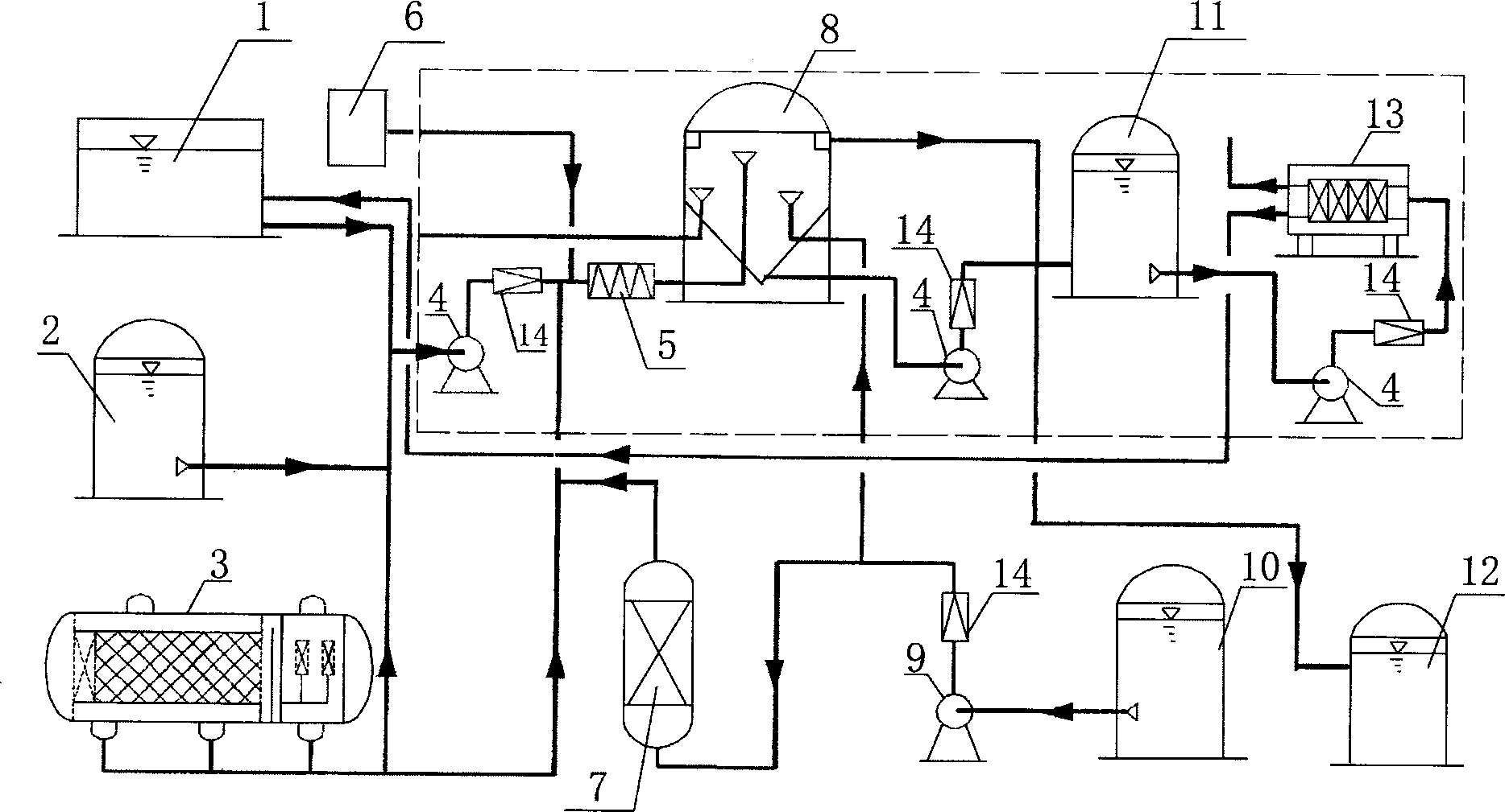
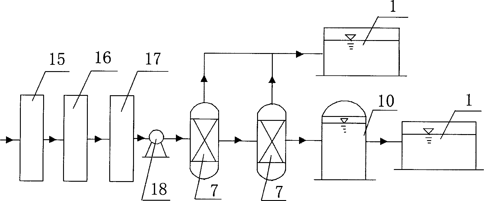
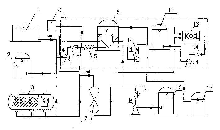
[0010] like figure 2 combine figure 1 As shown, the sludge concentration and dehydration treatment device includes a sewage recovery tank 1, a filter tank 7 and a clean water tank 10, and the sludge suction pipe at the bottom of the sewage recovery tank 1 is connected in parallel to the bottom sludge discharge pipe of the sedimentation separation equipment (2, 3), and then sequentially The sludge concentration tank 8 is connected to the sludge concentration tank 8 through the sludge lifting pump 4, the flow meter 14 and the pipeline mixer 5, and the concentration tank 8 is connected to the sludge storage tank 11 and the dewatering machine 13 in turn through the lifting pump 4 and the flow meter 14; The supernatant drain pipe of the tank 8 and the oil outlet pipe of the concentration tank 8 are respectively connected to the recovery tank 1 and the waste oil tank 12, and the clean water inlet pipe of the concentra...


PUM


Abstract

The sludge concentration dehydration treatment unit incldues a sewage recovery pool which is parallel to and communicated with settling separation equipment, then through sludge lifting pump and flowmeter, is connected with sludge concentration tank, slduge storage tank and dehydrating machine in turn; the dehydrating machine, supernatant fluid discharge pipe of the concentration tank and oil oultet pipe of the concentration tank are respectively connected with recovery pool and spump oil tank. It can prevent secondary pollution, and can raise sewage treatment efficiency.

Description

(1) Technical field: [0001] The invention relates to a device for treating sludge produced in oily sewage in an oil field, which belongs to a sludge concentration and dehydration treatment device. (two) background technology: [0002] At present, with the gradual deepening of oil field development, the waste of sewage and sludge is increasing continuously, and its composition is relatively complex, causing great harm to sewage treatment, reinjection and effluent, whether it is polymer flooding or ASP flooding It is also the treatment of oily sewage produced by conventional water flooding. Most oil-water mixtures pass through such as figure 2 Concentration and dehydration treatment of coagulation settling tank 15 and natural settling tank 16, so that the treated oil-water mixture is lifted by the buffer tank 17 and pump 18 and enters the continuous secondary filter tank 7 for filtration, and the separated water is recovered to the recovery Pool 1, but there is a problem of ...

Claims


Application Information

Patent Timeline
Patent Type & Authority Applications(China)
IPC IPC(8): C02F11/12
Inventor 夏福军陈忠喜张瑞泉马文铁才国忠罗兴仁韩丽华朱玉萍
Owner 大庆油田建设设计研究院
Why Eureka
Try Eureka