Structure mode of electro-mobile power and driving device

A technology for electric vehicles and transmissions, which is applied to electric power units, power units, vehicle components, etc., can solve the problems affecting the comfort and stability of the vehicle, increase the driving power of the vehicle, and the space occupied by the transmission. The effect of reduced weight, lower energy consumption and reduced maintenance effort

A technology for electric vehicles and transmissions, which is applied to electric power units, power units, vehicle components, etc., can solve the problems affecting the comfort and stability of the vehicle, increase the driving power of the vehicle, and the space occupied by the transmission. The effect of reduced weight, lower energy consumption and reduced maintenance effort

CN1392069AInactive Publication Date: 2003-01-22于耀庆

Image

  • Structure mode of electro-mobile power and driving device
  • Structure mode of electro-mobile power and driving device

Examples


Embodiment

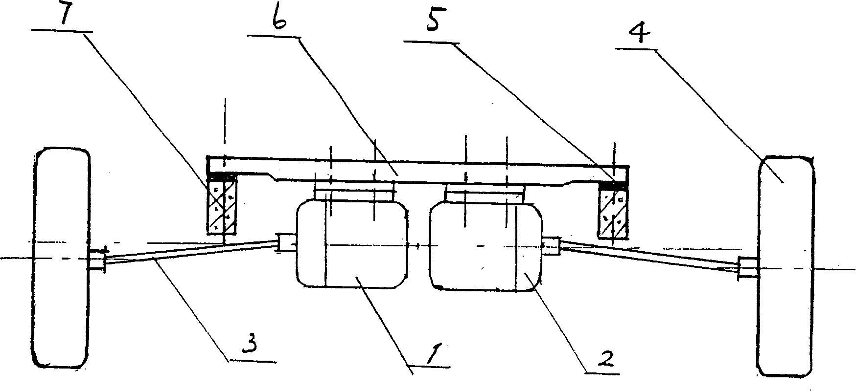
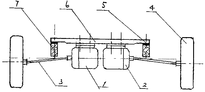
[0013] Example: Combine figure 1 Examples of the present invention will be described. The present embodiment is the power of a newly developed certain electric car and its transmission device. The body of the car is made of composite materials, with a curb weight of 1027kg. In the front power compartment, there are two longitudinal beams (7) connected to the left and right inner fenders, and the rear part is connected to the dash panel, which is the main load-bearing structure of the vehicle body. (5) Link to each other with the longitudinal beam of the vehicle body, two motors (1) are installed below the mounting bracket, because this motor is a high-speed motor n=8000r / m, the output end of the motor is equipped with an 8:1 planetary reducer (2), The output shaft of the speed reducer is provided with a ball cage of a constant velocity joint, and is connected with another ball cage inside the traveling wheel (4) through a transmission shaft. Since the motor is fixed on the ...


PUM


Abstract

The present invention relates to a new structure mode of power unit and drive unit and relates to the improvement of power unit and transmission system of electromobile. The present invention can raise the efficiency of the power unit and drive unit, reduce the weight of the power unit and drive unit and thus reduce the power consumption of the whole electromobile. The technological scheme is to use two drive motors to drive two front wheels separately via speed reducer and drive shaft. The structure is mainly used in electromobile.

Description

Technical field [0001] The invention relates to the improvement of electric vehicle power and transmission device. Background technique [0002] It goes without saying that electric vehicles are a future green and environment-friendly means of transportation. At present, the main obstacle restricting the commercial operation of electric vehicles is the energy structure. For pure electric vehicles, the specific energy of existing batteries is very low. Taking lithium-ion batteries with high energy storage efficiency as an example, the specific energy is 120-140W. H / kg, while the energy per kilogram of gasoline is 12400-13500W.H / kg, a difference of 100 times. For users, they will never use a vehicle with very poor power performance for the purpose of protecting the environment. This is also an important reason why it is difficult for pure electric vehicles to enter commercial operation, and thus become an invincible worldwide problem. [0003] At present, the development of...

Claims


Application Information

Patent Timeline
22 Jan 2003
Publication
CN1392069A
IPC
B60K1/02
Inventors
于耀庆; 于宾