Technology and die for machining part with internal screw hole

A technology of forming molds and processing methods, which is applied in the processing field of powder metallurgy parts and pass parts, can solve the problems of slow processing speed and high cost, and achieve the effects of improving efficiency, forming accurately, reducing processing time and process cost

Inactive Publication Date: 2003-02-19
ZHUZHOU HARD ALLOY GRP CO LTD
View PDF0 Cites 10 Cited by
  • Summary
  • Abstract
  • Description
  • Claims
  • Application Information

AI Technical Summary

Problems solved by technology

[0003] Aiming at the problems of slow processing speed and high cost in the above-mentioned prior art, the present invention provides a proces

Method used


Image

  • Technology and die for machining part with internal screw hole
  • Technology and die for machining part with internal screw hole
  • Technology and die for machining part with internal screw hole

Examples


Example Embodiment

[0018] The present invention will be described in detail below in conjunction with the accompanying drawings.

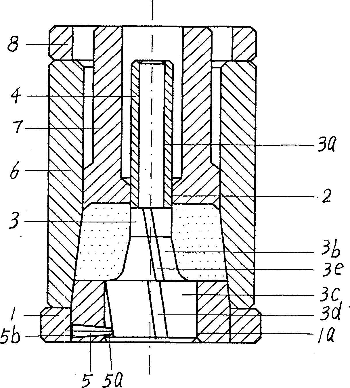
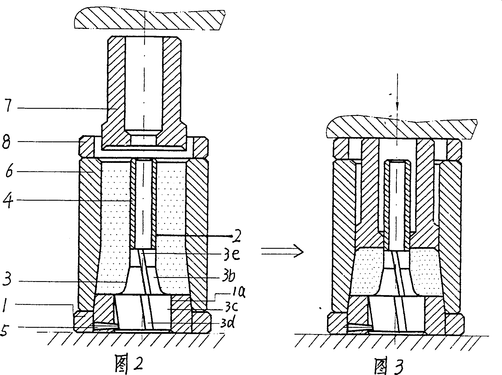
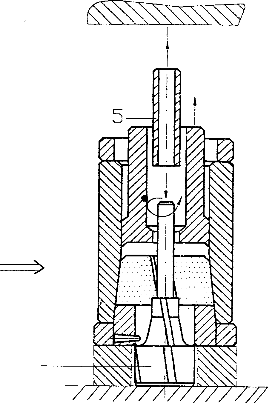
[0019] The part to be processed in this embodiment is a powder metallurgy part with four rectangular left helixes in the inner hole, its diameter is d, the helix angle is β, and the lead P=d×β. from figure 1 It can be seen that the specially designed molding die of the present invention is composed of a bottom pad 1, a core rod 2, a female mold 6, a punch 7, and a stop ring 8. The female mold 6 is placed on the bottom pad 1, and the stop ring 8 is placed on the female mold 6, one end of the core rod 2 passes through the central hole 1a of the bottom pad 1, the bottom pad 1, the female mold 6, the core rod 2, and the stop ring 8 are arranged coaxially; the core rod 2 is composed of the main core rod 3 and the auxiliary core rod 4 components, the main mandrel 3 includes a supporting area 3a, a forming area 3b, and a demoulding guide area 3c, the auxiliary mandrel 4 is...


PUM


Abstract

A technology for manufacturing the part with internal screw hole includes designing special die, precise die pressing and sintering. The said special die is composed of coaxially arranged bottom pad and combined core rod consisting of the primary core rod with external screw matched with said internal screw and demoulding spiral slot and the secondary core rod. The said bottom pad has the guide posts arranged radially and matched with said spiral slot. Its advantages are high utilziation rate of raw material high productivity and high shaping precision.

Description

Technical field: [0001] The invention relates to the processing of powder metallurgy part pass, in particular to a processing method for inner spiral pass part and a molding die for implementing the method. Background technique: [0002] The dies for drawing threaded rib steel and the drawing dies for automotive distributors and other pass parts belong to a kind of powder metallurgy parts with internal spiral pass. The blank is usually molded by powder, but with internal spiral grooves (tooth) When the preform of the shape is demoulded by the existing molding technology, the core rod cannot withdraw downwards, and withdrawing by force will destroy the inner screw hole. Therefore, the existing processing method is usually: first mold the powder material into a part blank with a light hole and leave a machining allowance, and then use the electrode corresponding to the inner spiral to EDM the inner spiral after sintering. This method can make the shape and size of the inner s...

Claims


Application Information

Patent Timeline
IPC IPC(8): B22F3/16B22F5/06B30B15/02
Inventor 李娜周清池刘诚
Owner ZHUZHOU HARD ALLOY GRP CO LTD
Why Eureka
Try Eureka