Laser roughening machine by laser focusing head array

A laser texturing and focusing head technology, applied in the field of laser texturing machines, can solve problems such as poor texturing uniformity, difficulty in connecting different areas, and low texturing efficiency

Inactive Publication Date: 2003-03-12
SHANGHAI INST OF OPTICS & FINE MECHANICS CHINESE ACAD OF SCI
View PDF0 Cites 12 Cited by
  • Summary
  • Abstract
  • Description
  • Claims
  • Application Information

AI Technical Summary

Problems solved by technology

Therefore, its disadvantage is that the texturing efficiency is low, and the texturing time is too long. Therefore, it is natural to think that multiple laser focusing heads should be used.
Since the spacing of the texturing pits is generally 150-200 μm, it is impossible to arrange the single laser focusing heads of a laser texturing machine with an average power of 100 watts in such an array. Due to the difference of several laser beams and the difficulty in connecting different areas, the uniformity of texturing is very poor

Method used


Image

  • Laser roughening machine by laser focusing head array
  • Laser roughening machine by laser focusing head array
  • Laser roughening machine by laser focusing head array

Examples


Embodiment Construction

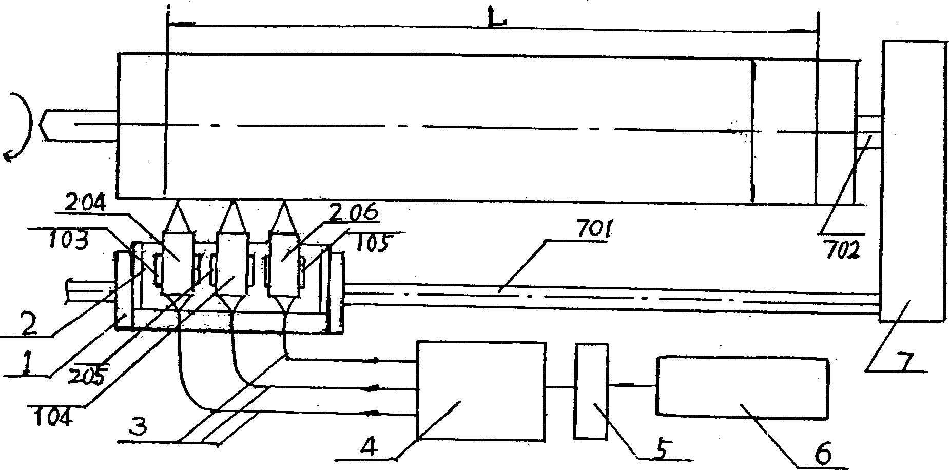
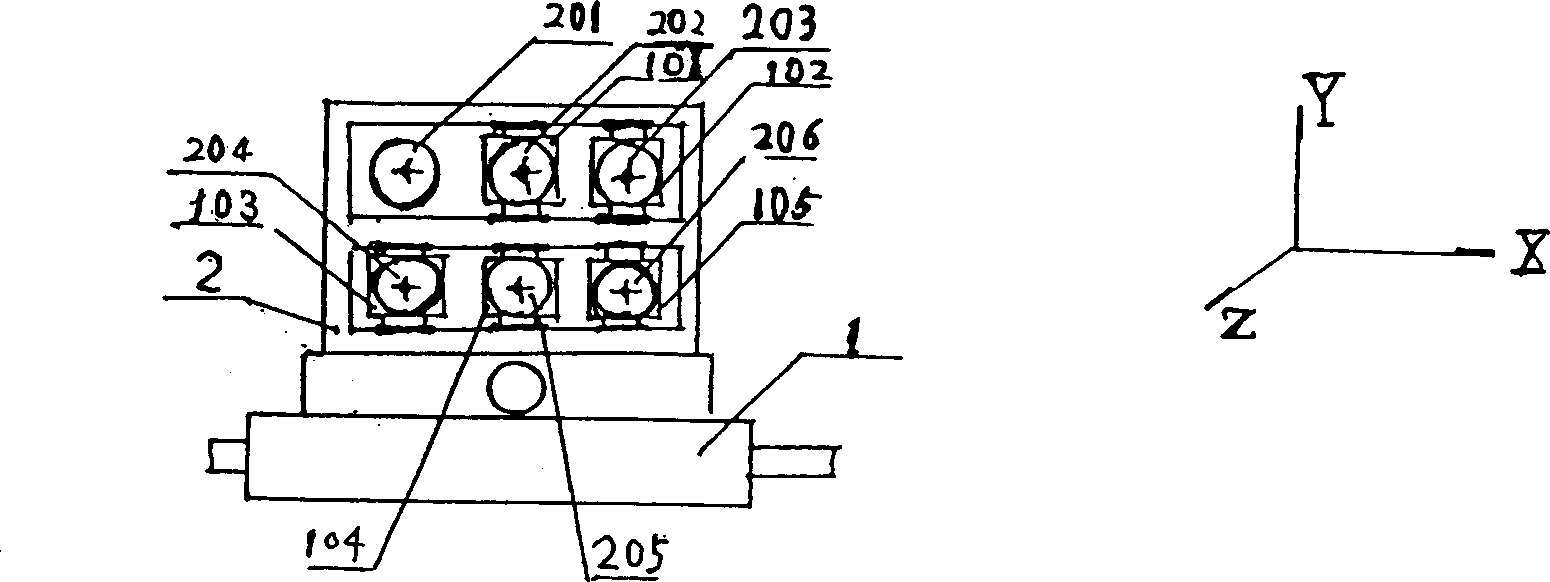
[0039] Such as Figure 7 structure shown. The laser 6 is an acousto-optic modulated Nd:YAG crystal laser. The laser amplifier 5 is a Nd:YAG crystal laser amplifier. The wavelength of the output laser beam is 1.06 μm. The beam splitter 5 is composed of a transflective plate 401 with 50% transmission and 50% reflection and a mirror 402 . Such as Figure 7-1 shown. The number of spotlight heads K=2, is a linear (oblique) array, such as Figure 7-2 shown.

[0040] The output beam of the acousto-optic modulated Nd:YAG laser 6 is amplified by the laser amplifier 5 , split into two paths by the beam splitter 4 , and then input to two laser focusing heads 201 and 202 respectively through two optical fibers 3 . Wherein the focusing head 201 is fixed on the working platform 1, and the working platform 1 is driven by the servo motor of the numerical control machine tool 7, and another focusing head 202 is installed on the small mobile platform 101 on the working platform 1, and th...


PUM


Abstract

A laser roughening machine with laser-gathering head array for metal surface, especially the surface of roller, is disclosed. The laser beam from laser device is amplified and then splitted into multiple beams, which are transmitted via relative optical fibres to the laser-gathering heads arranged by the form of rectangular, parallelogram or linear array on a small moving platform fixed the rotation shaft of numerally controlled machine-tool. After the roller to be roughened is fixed to the machine-tool and then rotating, the laser beams from said array scan on the surface of roller to generate pit matrix. Its advantages are short period and high uniformity of pit matrix.

Description

Technical field: [0001] The invention is a laser texturing machine adopting a laser focusing head array. Suitable for roughening of metal surfaces. Background technique: [0002] As we all know, the surface of the steel plate must be textured, and they are formed by pressing a textured roll. The surface texture of the roll was first formed by sandblasting. In the 1970s and 1980s, EDM technology appeared, and the discharge was used to form textured pits on the surface of the roll. Around the 1990s, laser technology was developed to focus the laser beam on the roll surface for roll texturing. This technology is called the third generation of texturing technology. Using pulsed CO 2 A laser or an acousto-optic modulated neodymium-doped yttrium aluminum garnet crystal (Nd:YAG) laser scans the focused laser in a helical manner on the roll surface to produce a regular distribution of textured pits on the surface. [0003] Compared with shot peening or EDM, laser texturing has...

Claims


Application Information

Patent Timeline
Patent Type & Authority Applications(China)
IPC IPC(8): B21B27/00B23K26/00B23K26/36
Inventor 王裕民于开义
Owner SHANGHAI INST OF OPTICS & FINE MECHANICS CHINESE ACAD OF SCI
Why Eureka
Try Eureka