Particle radius, concentration photosensor

An optical sensor and particle size technology, applied in the field of optical sensors, can solve the problems of difficult adjustment, restricted use, multi-phase flow flow field interference, etc., to achieve easy reception and processing, ensure safe use, and small flow field interference. Effect

Inactive Publication Date: 2003-04-16
SHANGHAI JIAO TONG UNIV
View PDF0 Cites 16 Cited by
  • Summary
  • Abstract
  • Description
  • Claims
  • Application Information

AI Technical Summary

Problems solved by technology

The most representative particle measurement technology is the diffraction laser particle size analyzer. After searching the literature, the latest product information of Malvern Company is published in www.malvern.co.uk In general, the diffraction laser particle size analyzer uses the distribution of particle diffracted light energy to calculate the particle size distribution. This kind of particle size analyzer is customarily called the Malvern instrument. Now there are reports for on-line measurement in industrial sites, but this A particle size analyzer based on the principle of diffraction has an insurmountable shortcoming when it is used for online measurement: to receive the diffracted light of the particles, a large receiving lens and a diffracted light receiving target are required, which makes the probe volume very large , the multiphase flow field will be strongly disturbed during online measurement; due to the large size of the lens, it is easy to be polluted by particles, and it is difficult to protect the lens; during the measurement, it must be ensured that the particle diffracted light is concentric with the ring light target, and it is difficult to adjust during use
Another kind of particle dynamic analyzer (English abbreviation PDA) was also found in the search, product information of DanTec company, website: www.dantecmt.com , it uses the phase difference of the scattered light on the particle after the intersection of two beams of light to realize the particle size measurement, because the phase information of the scattered light needs to be processed, the cost of the instrument is very high, the adjustment of the instrument is difficult, the requirements for the environment are high, and the optical path layout is lacking flexibility, which limits its use in harsh environments

Method used


Image

  • Particle radius, concentration photosensor
  • Particle radius, concentration photosensor
  • Particle radius, concentration photosensor

Examples


Embodiment Construction

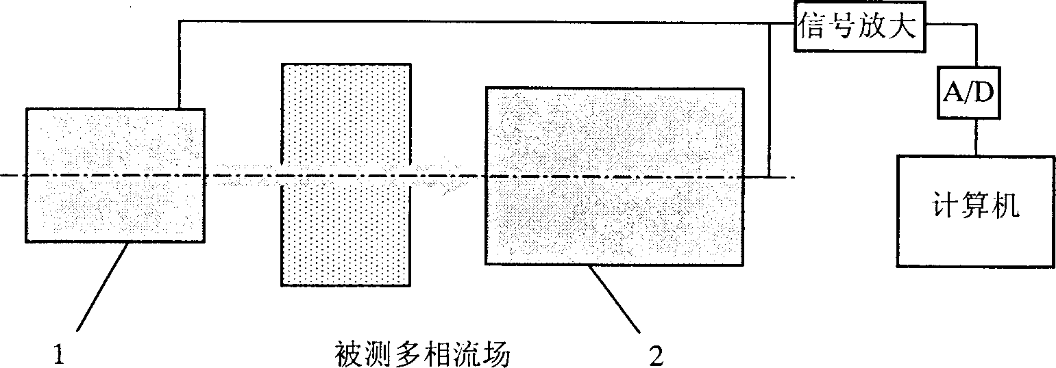
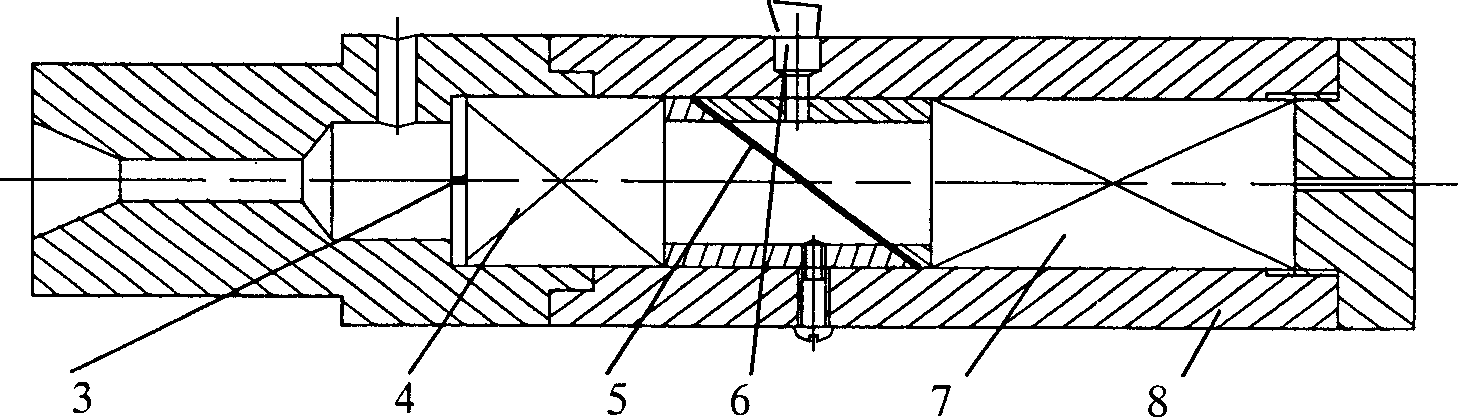
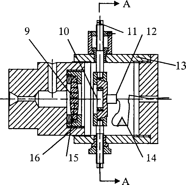
[0019] Such as figure 1 , figure 2 , image 3 and Figure 4As shown, the present invention adopts a separated group pair structure, that is, the present invention is composed of two parts, a transmitting end 1 and a receiving end 2, and the transmitting end 1 includes: a beam limiter 3, a spatial filter 4, a transmission-reflector 5, a reference The light receiving device 6, the semiconductor laser 7 and the cylindrical barrel 8 are connected in the following way: the beam limiter 3, the spatial filter 4, the transmission-reflecting mirror 5, and the semiconductor laser 7 are arranged in sequence and packaged in the cylindrical barrel 8 , the reference light receiving device 6 is fixed on the side wall of the cylindrical barrel 8, and is connected to the external circuit by wires; the receiving end 2 includes: a convex lens and a metal frame 9, an aperture 10, a two-dimensional adjustment device 11, and a photoelectric receiving device 12 , package body 13 and preliminary...


PUM


Abstract

The invention consists of two parts: the transmitting end and the receiving end. The transmitting end is composed of the beam limiting unit, the spatial filter, the transmission-reflector and semiconductor laser arranged in sequence encapsulated in the column shape barrel. The reference light receiver is fixed on the side wall of the column shaped barrel. The receiving end is composed of the convex lens, the metal frame, the diaphragm, the two-dimension adjusting unit, the photoelectric receiver and the packaging body. The preliminary signal multiplication circuit is encapsulated inside the packaging body. The invention can measure multiple parameters of the granules with less limitation for the object to be measured and little disturbing to the flow field.

Description

technical field [0001] The invention relates to an optical sensor, in particular to an optical sensor for particle size and concentration, and belongs to the field of measurement technology. Background technique [0002] In scientific research and industrial production, some applications require the measurement of particle size and concentration. Since particulate matter is almost involved in all industrial production and scientific research fields, universities, scientific research institutions and companies at home and abroad have done a lot of research work in this area in recent decades, achieved certain research results, and developed many particle measurement methods. Technologies and instruments, some of which have been commercialized and serialized. At present, the commonly used principles and technically mature multiphase flow particle measurement methods mainly include: optical method, electrostatic (capacitance or inductance) method, ultrasonic method, radioisoto...

Claims


Application Information

Patent Timeline
Patent Type & Authority Applications(China)
IPC IPC(8): G01N15/02G01N15/06G01N21/25G01N21/27
Inventor 吴伟亮陈汉平臧述升蔡小舒
Owner SHANGHAI JIAO TONG UNIV
Why Eureka
Try Eureka