D.C. current sensing device

A sensing device, DC current technology, applied in the direction of measuring device, voltage/current isolation, measuring current/voltage, etc., can solve problems such as complicated circuit debugging, and achieve high cost performance, good stability, and high measurement accuracy Effect

A sensing device, DC current technology, applied in the direction of measuring device, voltage/current isolation, measuring current/voltage, etc., can solve problems such as complicated circuit debugging, and achieve high cost performance, good stability, and high measurement accuracy Effect

CN1412568AInactive Publication Date: 2003-04-23HUAZHONG UNIV OF SCI & TECH

Image

  • D.C. current sensing device
  • D.C. current sensing device
  • D.C. current sensing device

Examples


Embodiment Construction

[0016] The present invention is further described now in conjunction with accompanying drawing.

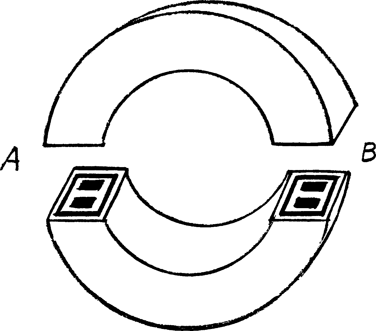
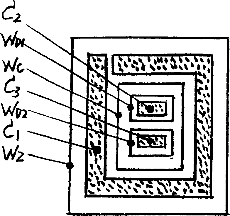
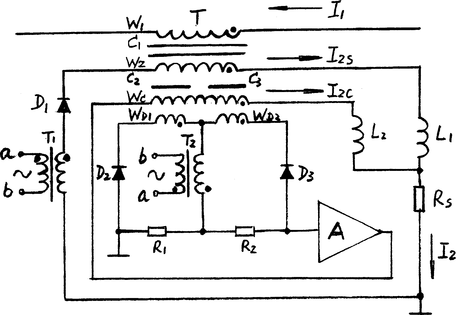
[0017] figure 1 As shown, the shape of the sensor head of the DC current sensor device is a circular ring composed of two half rings, and its cross-section is as follows figure 2 Shown: the first annular detection core C with the same shape 2 and the second annular detection core C 3 The first detection winding W with the same number of turns is respectively wound on D1 , the second detection winding W D2 , after assembling, wind the compensation winding W on the outside of them C , and then place them as a whole in the shielding iron core C with a ring cavity structure 1 in the cavity of the shielded core C 1 Then wind the secondary winding W 2 . image 3 The primary winding W shown 1 That is, the transmission of the measured DC current I 1 bus, from as figure 1 The sensor head shown passes through the center hole.

[0018] image 3 A circuit diagram of the DC curre...


PUM


Abstract

The D.C. current-sensing equipment incldues sensing head, power supply transformer, excitation transformer, resistor, inductor, diode, operation amplifier and driver, and its sensing head structure is characterized by that it has first ring detection iron core and second ring detection irno core, every iron core is equipped with first detecting winding and second detection winding which are identical in number of turns, after they are assembled, its exterior is equipped with compensation winding, its whole body is placed in shielding iron core hollow cavity, the exterior of the shielding ironcore is equipped with secondary winding. Said invention has the advantages of open-loop measurement and closed-loop measurement.

Description

technical field [0001] The invention belongs to the direct current measuring equipment in the electrotechnical field. Background technique [0002] Patent No. ZL 01219393.3 is a utility model patent "high-precision strong DC sensor". There is no magnetic core in the sensor housing, and the detection elements are evenly arranged in pairs along the inner periphery of the housing, and then filled with epoxy resin around the elements, and the detection elements fixed in the housing. The detection element directly detects the magnetic field generated by the bus current, and through the amplification of the circuit, the output signals of multiple detection elements are superimposed so that the output signal matches the data displayed on the test bench. This device has the common advantages of the open-loop principle, that is, there is no oscillation problem caused by the high voltage gain of the closed-loop system, and there is no high-power drive problem caused by maintaining th...

Claims


Application Information

Patent Timeline
23 Apr 2003
Publication
CN1412568A
IPC
G01R15/18; G01R19/00
Inventors
任士焱