Method for averaging plasma by using microwave electron cyclotron resonance

A technology of microwave electron cyclotron and electron cyclotron resonance, which is applied in the field of plasma, can solve the problems of plasma inhomogeneity, achieve the effect of simple manufacturing and installation, solve the problem of poor uniformity, and avoid complicated manufacturing and installation

Inactive Publication Date: 2003-05-07
BEIJING UNIV OF TECH
View PDF0 Cites 12 Cited by
  • Summary
  • Abstract
  • Description
  • Claims
  • Application Information

AI Technical Summary

Problems solved by technology

[0006] The purpose of the present invention is to propose a new method to solve the problem of plasma inhomogeneity in the field of electron cyclotron resonance plasma application technology

Method used


Image

  • Method for averaging plasma by using microwave electron cyclotron resonance
  • Method for averaging plasma by using microwave electron cyclotron resonance
  • Method for averaging plasma by using microwave electron cyclotron resonance

Examples


example 1

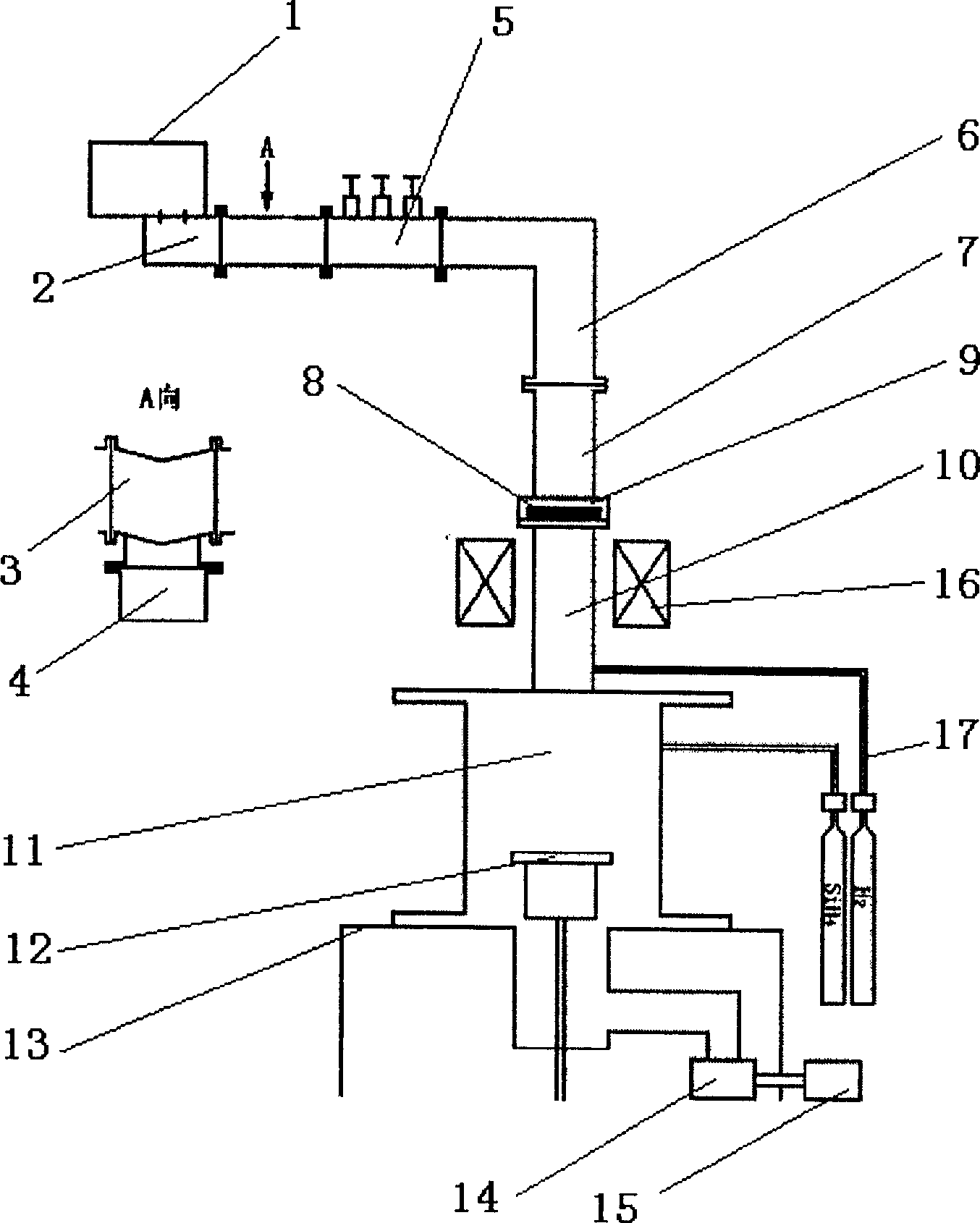
[0029] Example 1: The experimental condition is that the system is evacuated to 1×10 -3Pa, hydrogen gas is passed into the resonant cavity 10 with a flow rate of 20 sccm, the air pressure is adjusted to 0.5 Pa, a current of 137A is passed into the magnetic field coil 16, and the actual output power of the microwave source is 500W. Under the joint action of the microwave and the magnetic field of the coil, electron cyclotron resonance plasma can be generated in the resonant cavity 10 .

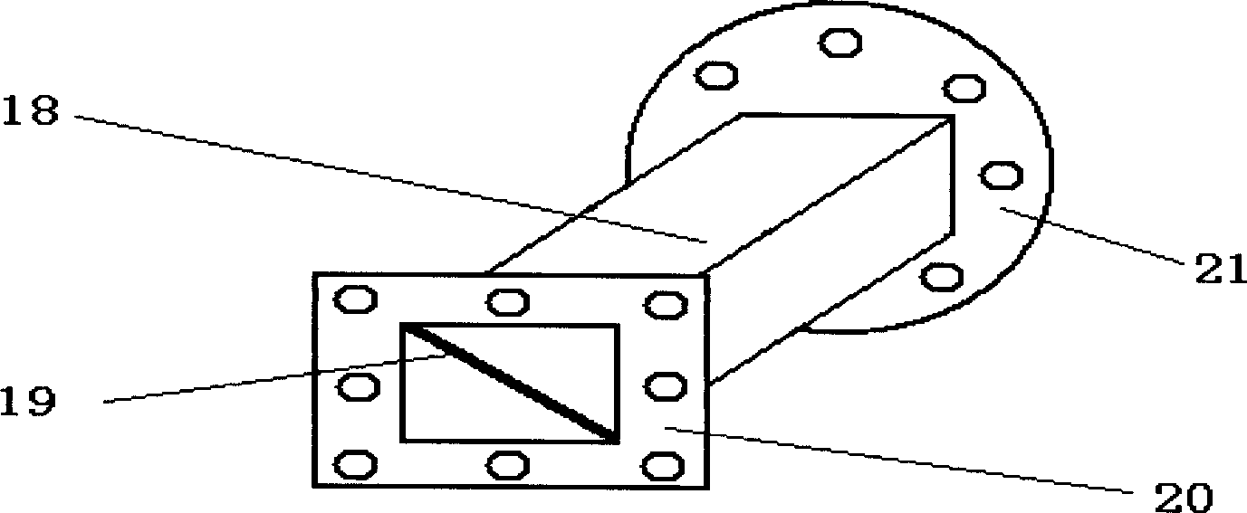
[0030] image 3 and Figure 4 Plasma photos using rectangular waveguides and double triangular waveguides, respectively. , the glow of the plasma using a rectangular waveguide has alternating light and dark areas from the resonator to the deposition chamber, indicating that the plasma distribution is very uneven. After using the double-triangular waveguide, no bright and dark areas can be seen in the plasma glow from the resonator to the deposition chamber, indicating that the plasma distrib...

example 2

[0031] Example 2: Put a clean glass sheet with a size of 80mm×80mm×1mm on the sample stage 12, and the system is vacuumed to 1×10 -3 Pa, heat the sample to 280°C, feed hydrogen into the resonant cavity with a flow rate of 20 sccm, feed silane into the deposition chamber 11 with a flow rate of 7 sccm, adjust the total air pressure to 0.5 Pa, feed a current of 137A into the magnetic field coil 16, and microwave source The actual output power is 500W. Under the joint action of microwave and coil magnetic field, electron cyclotron resonance plasma is generated in the resonant cavity and deposition chamber, and the amorphous silicon film is deposited on the glass sheet. The deposition time was 1 hour.

[0032] Checking the film thickness found that within the diameter range of φ60mm, the film thickness of the amorphous silicon film obtained by using a rectangular waveguide is 1.40μm~1.92μm, and the film thickness varies by 36%, which indicates that the corresponding silane plasma ...


PUM


Abstract

The invention belongs to the microwave low-temperature plasma. Microwave through dual triangle typed wave-guide tube with their relation of rotated 180 degrees generates the two beam of microwave, then passing through the coupling of the microwave window entering to the resonant cavity. The two beam of microwave are superposed in the resonant cavity, forming the new two-beam microwave field. The wave-guide tube is designed as follows: The equipartition plate is inserted to the section of the rectangular wave-guide, which is positioned between the ceramics microwave window 8 and the flange 9 of the window so as to form the dual triangle typed wave-guide tube. The invention solves the problem of the uneven plasma, and features installation and no pollution for the plasma.

Description

technical field [0001] A method and device for homogenizing microwave electron cyclotron resonance plasma belong to the technical field of microwave low-temperature plasma. Background technique [0002] Electron cyclotron resonance (ECR) plasma is a new type of microwave plasma developed in the past ten years. Due to its high degree of ionization and no electrode pollution, it has been paid more and more attention by people. However, most of the microwave electron cyclotron resonance devices currently used at home and abroad have a certain degree of inhomogeneity in the generated plasma. [0003] The main reason for plasma inhomogeneity is: Microwave electron cyclotron resonance equipment generally uses 2.4 5G microwaves, and almost all of them use TE 10 (that is, the transverse electric mode of the rectangular waveguide, which is also the main wave of the rectangular waveguide) to transmit, TE 10 After the microwave is coupled into the cylindrical resonator through the w...

Claims


Application Information

Patent Timeline
Patent Type & Authority Applications(China)
IPC IPC(8): H05H1/30
Inventor 阴生毅陈光华
Owner BEIJING UNIV OF TECH
Why Eureka
Try Eureka