Method for quick resistance trimming by using laser on printed circuit board directly

A printed circuit board and laser resistance trimming technology, which is applied in the fields of printed circuit, printed circuit manufacturing, circuit, etc., can solve the problems of manufacturing troubles, time-consuming and labor-intensive testing errors, and the inability to improve the product quality rate.

Inactive Publication Date: 2003-05-07
李俊豪
View PDF0 Cites 16 Cited by
  • Summary
  • Abstract
  • Description
  • Claims
  • Application Information

AI Technical Summary

Problems solved by technology

[0003] However, due to the slow speed of manual testing and resistance adjustment, it increases the complexity of the manufacturing process, and is time-consuming and labor-intensive. Especially manual testing is not only expensive, but also increases manufacturing costs, and is prone to test errors caused by human factors. Improve product quality
[0004] In addition, in the past, a method of chip resistors pasted on a printed circuit board by surface mount technology (SMT) was: first print carbon films or metal films arranged in columns on a ceramic board, and then use a laser trimmer to process Adjust the resistance, and then cut into grains by dicing, then package the upper electrodes of each grain to form chip resistors, and finally, stick the chip resistors on a printed circuit board with a chip mounter. Positioning on the circuit board, however, this production method still has the following problems, which cause troubles in manufacturing:
[0005] 1. Because printed circuit board manufacturers need to purchase various resistors from chip resistor manufacturers in advance, it will cause inventory pressure and management difficulties
[0006] 2. If the resistance value of the resistor is temporarily changed, the printed circuit board manufacturer needs to re-order, resulting in a stagnation of the production process
[0007] 3. The cost of chip resistors is more expensive

Method used


Image

  • Method for quick resistance trimming by using laser on printed circuit board directly
  • Method for quick resistance trimming by using laser on printed circuit board directly
  • Method for quick resistance trimming by using laser on printed circuit board directly

Examples


Embodiment Construction

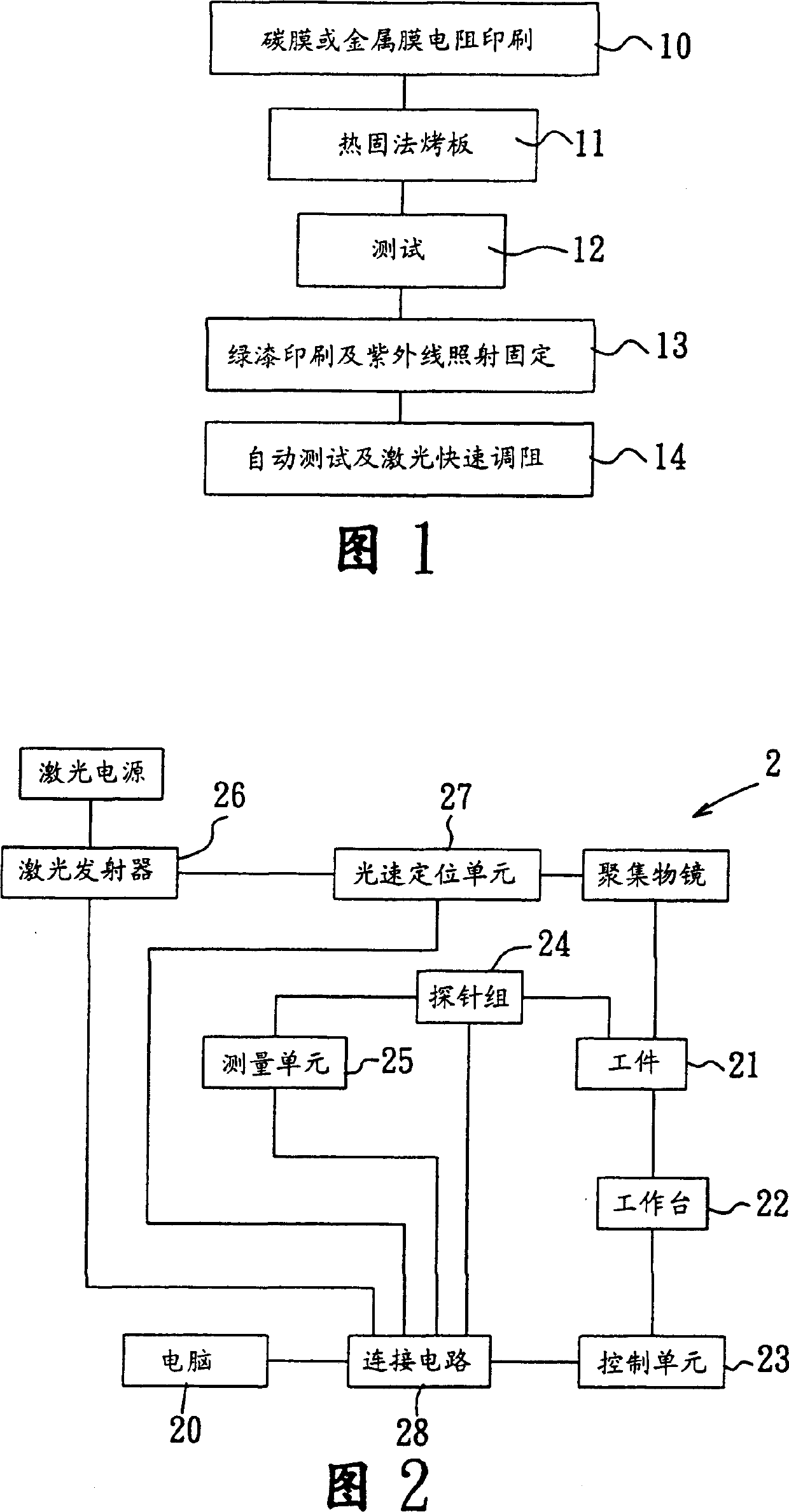
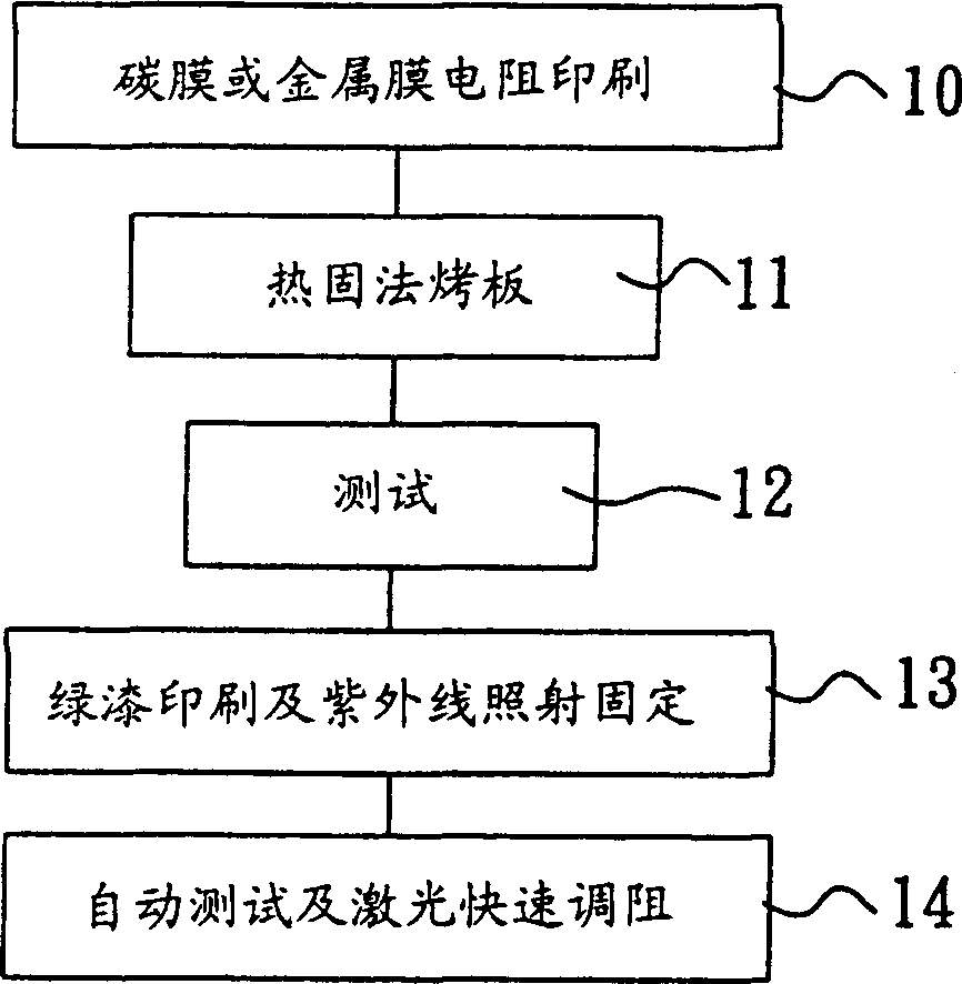
[0016] Referring to FIG. 1 , it shows a preferred embodiment of the method of direct laser trimming on a printed circuit board according to the present invention. Generally, there are two ways to layout (layout) resistors on a printed circuit board, one of which is to directly paste individual (resistance adjusted) chip resistors on the printed circuit board by means of surface mount technology (SMT). . The other is to directly print thick / thin film resistors on the printed circuit board, and then test and adjust the resistance of the resistors, and this printed circuit board with thick / thin film resistors is the adjustment method of this embodiment. The object on which the blocking method is to be implemented. The method of this embodiment includes: a. First, provide a printed circuit board printed with several thick / thin film resistors. As shown in block 10 to block 13 in Figure 1, the process of manufacturing a printed circuit board with several thick / thin film resistors ...


PUM


Abstract

The printed circuit board (PCB) with several resistance being printed on it is put on it is put on the laser resistance adjustment device. The device measures the value of the resistance on the PCB, and the value of the resistance is adjusted by using the laser beam. The method features adjusting the resistance rapidly, shortening the measurement time, and raising the quality rate.

Description

【Technical field】 [0001] The invention relates to a method for quickly adjusting resistance directly by laser on a printed circuit board. 【Background technique】 [0002] The traditional process of printing thick / thin film resistors (for example, carbon film or metal film resistors) on a printed circuit board is: first print a carbon film or metal film resistor on the printed circuit board, and then print the printed circuit board with After the resistance is preliminarily fixed by thermosetting baking, the circuit board is tested, and then green paint is printed on the printed circuit board and irradiated with ultraviolet (UV) to insulate from the outside and further fix the circuit board. Afterwards, the resistance value of the resistance is measured and adjusted by manual testing, so that the resistance value of the resistance on the printed circuit board can reach a certain accuracy. [0003] However, manual testing and resistance adjustment are not only slow, increase t...

Claims


Application Information

Patent Timeline
Patent Type & Authority Applications(China)
IPC IPC(8): H01C17/065H01C17/242H05K1/16H05K3/00
Inventor 李俊豪
Owner 李俊豪
Why Eureka
Try Eureka