
Dielectric procelain composition and electronic parts

A technology of dielectric ceramics and electronic devices, which is applied in the field of multilayer ceramic capacitors or other electronic devices, can solve the problems such as the easy reduction of insulation resistance life, and achieve the maintenance of insulation resistance life, high specific permittivity, and small capacitance aging characteristics Effect

Inactive Publication Date: 2003-06-18
TDK CORPARATION
View PDF4 Cites 5 Cited by
  • Summary
  • Abstract
  • Description
  • Claims
  • Application Information

AI Technical Summary

Problems solved by technology

[0018] However, in the dielectric ceramic composition of the above invention, the present inventors proved that when the dielectric layer is made thinner, it is difficult to make the capacitance-temperature characteristic satisfy the X8R characteristic and the insulation resistance life tends to decrease

Method used


Image

  • Dielectric procelain composition and electronic parts
  • Dielectric procelain composition and electronic parts
  • Dielectric procelain composition and electronic parts

Examples


example 1

[0126] Production of capacitor samples

[0127] First, as a starting material for preparing a dielectric substance, a main component material (BaTiO 3 ) and first to fifth subcomponents having an average particle diameter of 0.1 to 1 micron, respectively. Use carbonate (first subcomponent: MgCO 3 , the fourth subcomponent: MnCO 3 ) for MgO and MnO materials, using oxides (second subcomponent: Y 2 o 3 , the third subcomponent: (Ba 0.6 Ca 0.4 ) SiO 3 , the fifth subcomponent: V 2 o 5 ) as other materials. Note that by using ball milling for BaCO 3 , CaCO 3 and SiO 2 Wet mixing was carried out for 16 hours, drying, firing in air at 1150 °C, and additional wet grinding using a ball mill for 100 hours, thus preparing (Ba 0.6 Ca 0.4 ) SiO 3 .

[0128] Note that by weighing BaCO separately using 3 and TiO 2 Prepare the main component BaTiO 3 , performed wet mixing using a ball mill for 16 hours, dried, fired at 1100°C in air, and further wet milled using a ball mil...

example 2

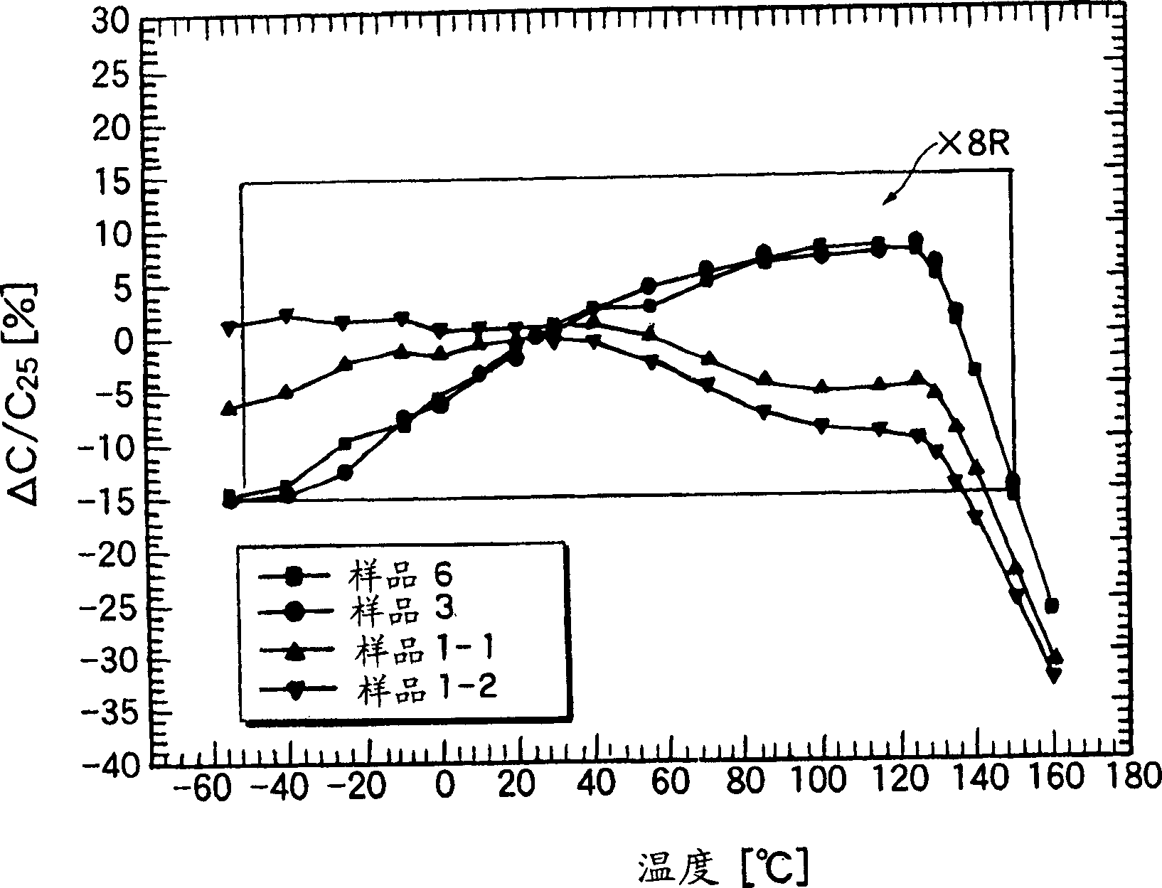
[0169] Capacitor samples were prepared in the same manner as Sample 3 of Example 1, except that the contents of the first subcomponent were changed to 0 mol (sample 6), 0.08 mol (sample 3), 1.0 mol (sample 1-1), and 2.06 mole (sample 1-2).

[0170] Capacitance was measured within a temperature range of -55 to 160°C, and the rate of change (ΔC / C) at each temperature was calculated relative to the capacitance at +25°C. The results are plotted in Table 2. As shown in Table 2, it was confirmed that when the content of the first subcomponent was reduced, the capacitance-temperature change rate on the high temperature side became small. That is, it has been confirmed that by decreasing the content of the first subcomponent, the plot points of the capacitance-temperature change rate on the high temperature side can be drawn in the counterclockwise direction of the graph.

example 3

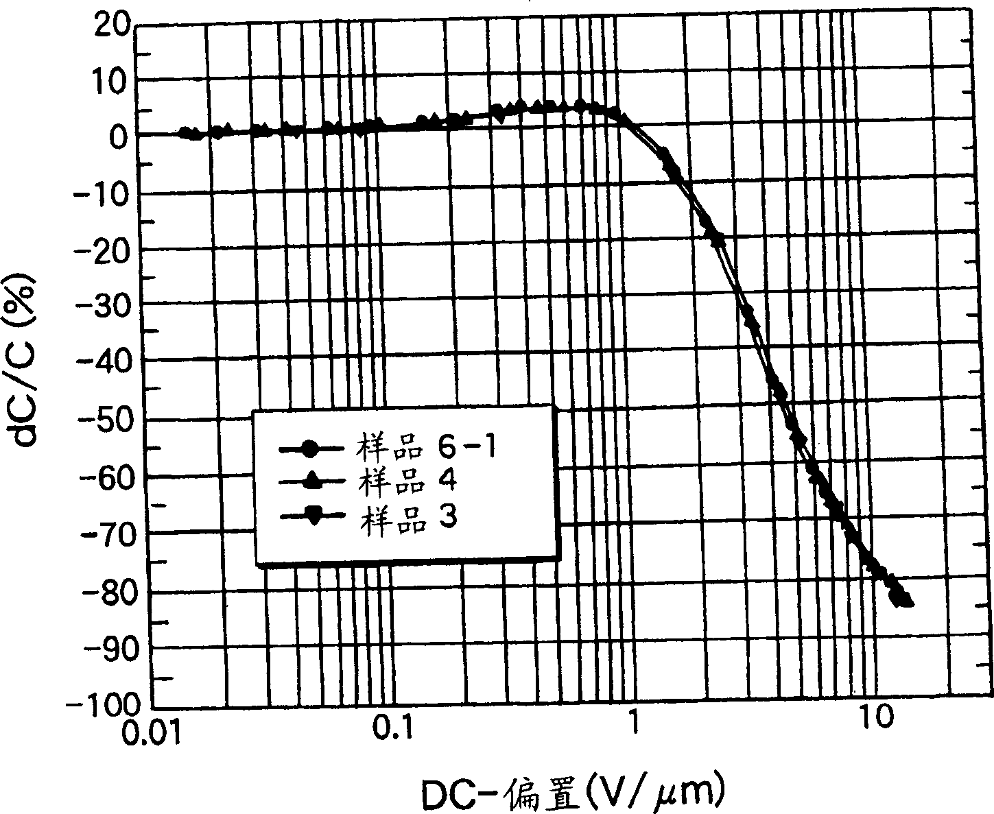
[0172] Capacitor samples were prepared in the same manner as Sample 3 of Example 1, except that the content of the first subcomponent was changed to 0.02 mol (sample 6-1), 0.04 mol (sample 4) and 0.08 mol (sample 3).

[0173] DC bias characteristics (depending on DC voltage application and dielectric constant) were evaluated from capacitor samples.

[0174] DC bias characteristics (dependence on DC voltage application and dielectric constant)

[0175] The DC bias characteristics were obtained by measuring the capacitance change (ΔC / C) by gradually applying a DC voltage to each capacitor sample at a constant temperature (25°C). The results are shown in image 3 . Such as image 3 As shown, it has been confirmed that when the content of the first subcomponent is within the range of the present invention, even if a high voltage is applied, the capacitance is hardly reduced, resulting in stable DC bias characteristics.


PUM

PropertyMeasurementUnit
sizeaaaaaaaaaa
thicknessaaaaaaaaaa

Abstract

A dielectric porcelain composition which comprises a main component comprising barium titanate, a first auxiliary component comprising an AE oxide (wherein AE represents at least one selected from among Mg, Ca, Ba and Sr) and a second auxiliary component comprising an R oxide (wherein R represents at least one selected from among Y, Dy, Ho and Er), wherein the amounts of the first auxiliary component and the second auxiliary component relative to 100 moles of the main component are 0 mole < the first auxiliary component < 0.1 mole and 1 mole < the second auxiliary component < 7 mole, respectively. The composition exhibits an elevated relative permittivity, can retain initial insulation resistance for a long period of time, exhibits a capacity-temperature characteristic satisfying the X8R characteristic of EIA specification, and can be subjected to a firing treatment in a reducing atmosphere.

Description

technical field [0001] The present invention relates to a dielectric ceramic composition for reducing resistance, and to a multilayer ceramic capacitor or other electronic devices using the dielectric ceramic composition. Background technique [0002] A multilayer ceramic capacitor is an electronic device that is widely used as a compact, large-capacity, high-reliability electronic device. The number of capacitors used in each electronic device is also increasing. In recent years, with the increasing miniaturization and performance improvement of devices, there has been an increasing demand for further reduction in size, increase in capacity, reduction in price, and improvement in reliability of multilayer ceramic capacitors. [0003] Generally, a paste for internal electrode layers and a paste for dielectric layers are stacked using a sheet method or a printing method, and then the stacked internal electrode layers and dielectric layers are co-fired to...

Claims


Application Information

Patent Timeline
Patent Type & Authority Applications(China)
IPC IPC(8): C04B35/468C04B35/638H01G4/12
CPCB32B38/145C04B2235/5445C04B2235/3454C04B2235/3239C04B2235/3409C04B2235/3206C04B2237/40C04B35/6303C04B2235/3293C04B2235/3215C04B2237/704C04B2235/3217C04B2235/79B32B2038/0064C04B2235/6582C04B35/6264C04B2235/3213C04B35/468B32B2311/12C04B2235/3249C04B2235/3203C04B2235/3262C04B2235/3224C04B2237/407C04B2235/785C04B2235/6583B32B2311/22C04B2237/403C04B2237/706C04B35/624C04B2235/663C04B2235/3205C04B35/4682C04B2235/3208C04B2235/3427C04B2237/50C04B2237/405C04B35/638C04B2235/786C04B35/64C04B2237/12C04B2235/3436C04B2235/3258H01G4/1227C04B2235/3241C04B2235/5436C04B2235/3256C04B2235/3225B32B18/00C04B2235/3244C04B35/46H01B3/12
Inventor 小林央始内田知子佐藤茂树野村武史
Owner TDK CORPARATION
Learn More