Photoelectronic integrated acceleration geophone

A geophone and optoelectronic integration technology, applied in the direction of seismic signal receivers, etc., can solve the problems of narrow frequency band, low sensitivity, large geophone volume, etc., and achieve the effects of low-cost mass production, anti-electromagnetic interference, and high sensitivity

Inactive Publication Date: 2003-06-25
TIANJIN UNIV
View PDF0 Cites 22 Cited by
  • Summary
  • Abstract
  • Description
  • Claims
  • Application Information

AI Technical Summary

Problems solved by technology

[0002] At present, most of the traditional electromagnetic geophones are used in the field of seismic exploration. Such geophones are large in size, low in sensitivity, narrow in frequency band, and are suscept

Method used


Image

  • Photoelectronic integrated acceleration geophone
  • Photoelectronic integrated acceleration geophone
  • Photoelectronic integrated acceleration geophone

Examples


Embodiment Construction

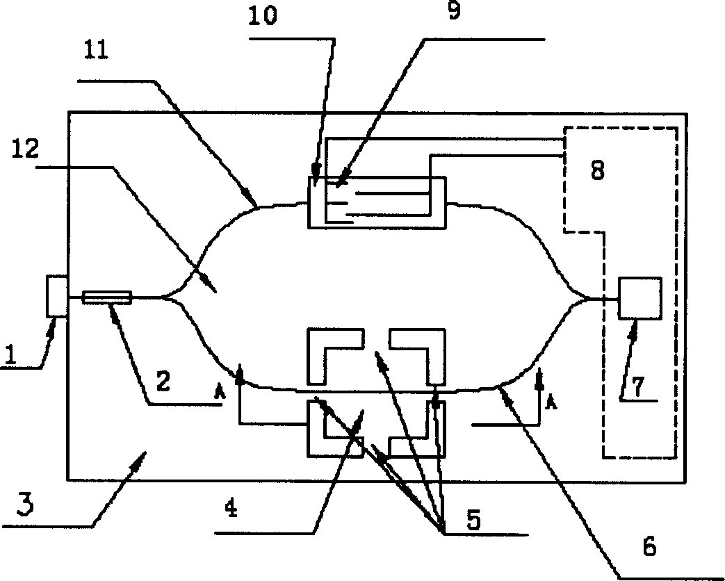
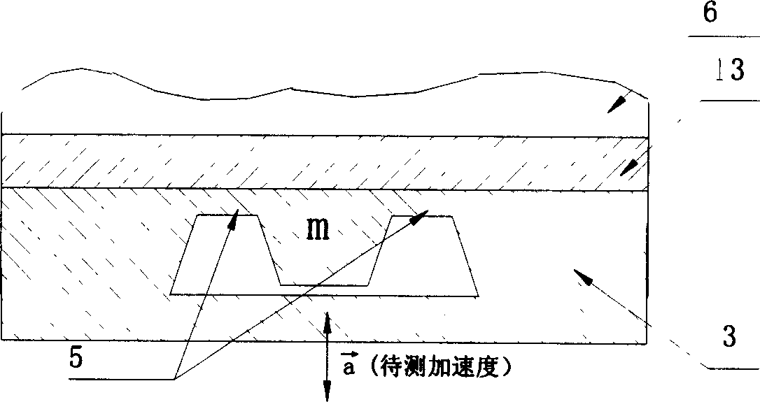
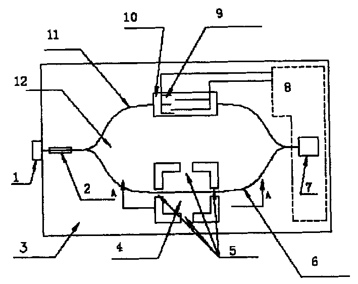
[0008] On the silicon substrate 3, the quality block 4 of the cross beam structure is etched out, and the silicon dioxide buffer layer 13 is sputtered on the silicon substrate, and the waveguide M-Z interferometer 12 is fabricated on the silicon dioxide buffer layer (the signal arm of the interferometer passes through the cross beam one). When the natural light emitted by the semiconductor laser 1 is coupled into the input end of the M-Z interferometer, it becomes polarized light after passing through the waveguide polarizer 2, and enters the two arms 6 and 11 of the M-Z interferometer in two paths. Due to the vibration of the mass block, the light phase in the signal arm 6 changes. When the two beams of light propagating in the arms 6 and 11 converge at the output end of the M-Z interferometer to form interference, their light intensity is detected by the photodetector 7. After being processed by the signal processing circuit 8 integrated on the silicon base, the high-precisi...


PUM


Abstract

The photoelectronic integrated acceleration geophone is one acceleration and seismic wave detector. Inside metal casing, there are photoelectronioc integrated acceleration geophone chip and laser. The chip consists of silicon substrate, buffering silica layer and integrated optical waveguide polarizer, M-Z waveguide interference instrument, interdigital photoacoustic transducer, photoelectronic detector, temperature compensator and demodulator circuit and signal processor circuit; and has simple harmonic vibrator comprising cross beam etched on the silicon substrate and silicon mass block. The present invention features the connection of the input of the M-Z waveguide interference instrument and the laser, the connection of the output and the photoelectronic detector, and the connection of the signal arm with planar waveguide and the photoacoustic transducer.

Description

technical field [0001] The invention relates to a photoelectric integrated acceleration geophone, belonging to acceleration and seismic wave detection devices. Background technique [0002] At present, traditional electromagnetic geophones are mostly used in the field of seismic exploration. Such geophones are large in size, low in sensitivity, narrow in frequency band, and are susceptible to electromagnetic interference. The fiber optic acceleration detector has also been reported, but there is a contradiction between the improvement of its stability and the cost, and the volume is too large. Contents of the invention [0003] The object of the present invention is to provide a photoelectric integrated geophone, which has the characteristics of wide test frequency band, high sensitivity, good fidelity, anti-electromagnetic interference, low cost and miniaturization. [0004] The technical scheme adopted by the present invention to solve its technical problems is: a photo...

Claims


Application Information

Patent Timeline
IPC IPC(8): G01V1/18G01V1/20
Inventor 陈才和
Owner TIANJIN UNIV
Why Eureka
Try Eureka