Device and method for light-modulating control of fluorescent lamp

A technology of dimming control and fluorescent lamps, which is applied in many fields with advantages of low electromagnetic interference and low switching stress, and can solve the problems of high cost, increased switching loss of inverters, complex frequency conversion control, etc., and achieves reduced manufacturing costs and small voltage ratings , The effect of small switching loss

Inactive Publication Date: 2003-08-13
CITY UNIVERSITY OF HONG KONG
View PDF0 Cites 8 Cited by
  • Summary
  • Abstract
  • Description
  • Claims
  • Application Information

AI Technical Summary

Problems solved by technology

[0015] 1. Frequency conversion control is more complicated and expensive than constant frequency control;
[0016] 2. If the inverter is not operated with soft switching, the switching loss of the inverter will increase, thereby reducing the system efficiency;
[0017] 3. In order to adjust the lamp to low power output, the switching frequency range may be very large (for example: 25kHz ~ 65kHz), but in fact the frequency range of the magnetic core, the gate drive circuit and the electronic control circuit will limit the dimming frequency range;
[0018] 4. It is difficult to realize soft switching in the whole frequency modulation range
[0019] 5. If the switching frequency range is small, the power adjustment range is small

Method used


Image

  • Device and method for light-modulating control of fluorescent lamp
  • Device and method for light-modulating control of fluorescent lamp
  • Device and method for light-modulating control of fluorescent lamp

Examples


Embodiment Construction

[0054] In the present invention, the DC output voltage of the converter is variable, and by adjusting the DC output voltage, smooth and good fluorescent lamp dimming control can be obtained. Depend on Figure 6 It can be seen that between the input power supply and the half-bridge inverter is a power converter, which provides a variable DC input voltage for the half-bridge inverter. Figure 6 In is the AC input power supply, so the converter is an AC-DC converter, Figure 7 In is the DC input power supply, so the converter is a DC-DC converter.

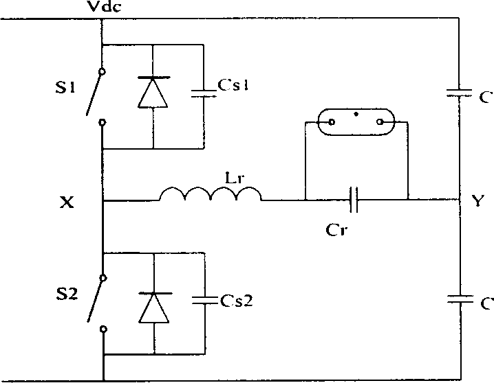
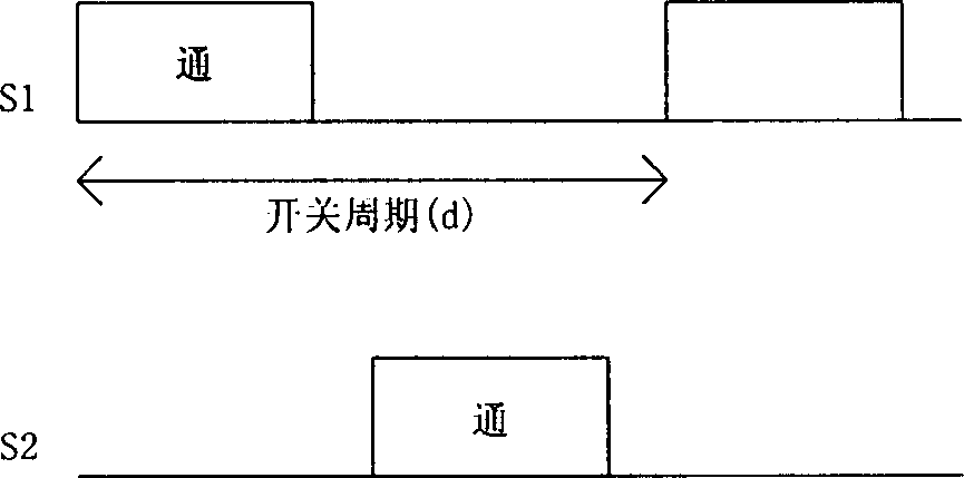
[0055] In the present invention, in order to control the output voltage of the lamp, the DC output voltage V of the front-end converter DC is controllable. In order to ensure a wide power regulation range and continuous inductor current conditions required for soft switching, the duty cycle of the switches of the half-bridge inverter is kept constant (close to 0.5). And this also makes the control simple. The switching frequency ...


PUM


Abstract

A circuit structure and control method for controlling the light modulation of fluorescent lamp is disclosed. Said fluorescent lamp is driven by a semi-bridge resonant inverter type ballast working in constant frequency and constant duty ratio. Changing the DC input voltage of said ballast can modulate the light. Its variable DC power supply is taken from AC-DC converter for AC input power supply or DC-DC converter for DC input power supply.

Description

technical field [0001] The invention relates to the related problems of the dimming control method and equipment of the electronic ballast for fluorescent lamps, and particularly relates to the advantages of low electromagnetic interference and low switch stress brought by the equipment and the control method. Background technique [0002] As an energy-saving measure for residential, commercial and industrial lighting, high-frequency electronic ballasts for fluorescent lamps are gradually being widely used. Electronic ballasts have many advantages such as: increased efficiency, higher output luminosity and longer life of fluorescent lamps. Electronic ballasts are switch-mode power circuits, generally using series resonant power converters. [0003] figure 1 The basic principle of the traditional electronic ballast is drawn. At a higher frequency (usually 25kHz ~ 50kHz), the resonant capacitor C r The voltage on will turn the lamp on. Due to the high frequency of the driv...

Claims


Application Information

Patent Timeline
Patent Type & Authority Applications(China)
IPC IPC(8): H05B41/282H05B41/38
Inventor 许树源钟树鸿
Owner CITY UNIVERSITY OF HONG KONG
Why Eureka
Try Eureka