Power circuit and method for controlling same circuit

A power supply circuit and power control technology, applied in battery circuit devices, circuit devices, systems that store electrical energy, etc., can solve problems such as the inability to operate the battery fully and effectively, the inability to use current, the difficulty of matching the minimum driving voltage and the discharge termination voltage, etc.

Inactive Publication Date: 2003-09-03
TOKIN CORP
View PDF1 Cites 15 Cited by
  • Summary
  • Abstract
  • Description
  • Claims
  • Application Information

AI Technical Summary

Problems solved by technology

[0007] However, in the case of such portable devices whose load varies with time, such devices specifically refer to digital devices popular in recent years as devices operating according to the TDMA (Time Division Multiple Access) method, such as digital data transmission systems, because their batteries The voltage varies with time, and matching between the minimum driving voltage and the end-of-discharge voltage becomes difficult, so the problem with conventional power supply circuits is that they cannot operate the battery fully efficiently
[0008] Also, in the case of a device powered by power from a personal computer serving as a host according to USB (Universal Serial Bus) which is an Internet specification, since there is an upper limit to the current used in USB, a device that consumes more current than the upper limit cannot be used. current device
[0009] Therefore, the problem of the conventional power supply circuit is that it is impossible to effectively use the battery serving as the power supply, and the current exceeding the limit value cannot be used

Method used


Image

  • Power circuit and method for controlling same circuit
  • Power circuit and method for controlling same circuit
  • Power circuit and method for controlling same circuit

Examples


no. 1 example

[0067] Next, the detailed structure of the power supply circuit having the first basic configuration is further described.

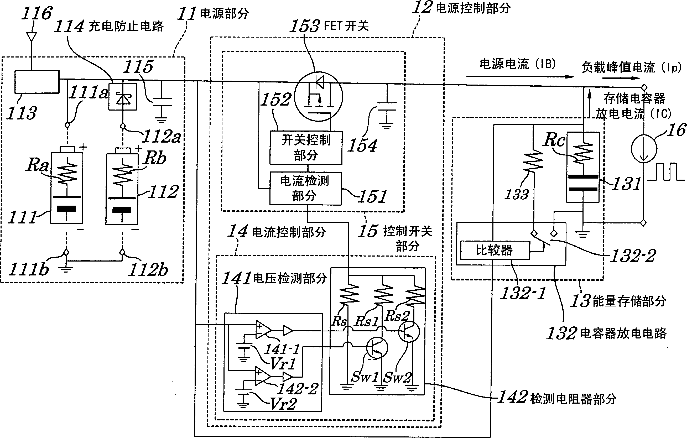
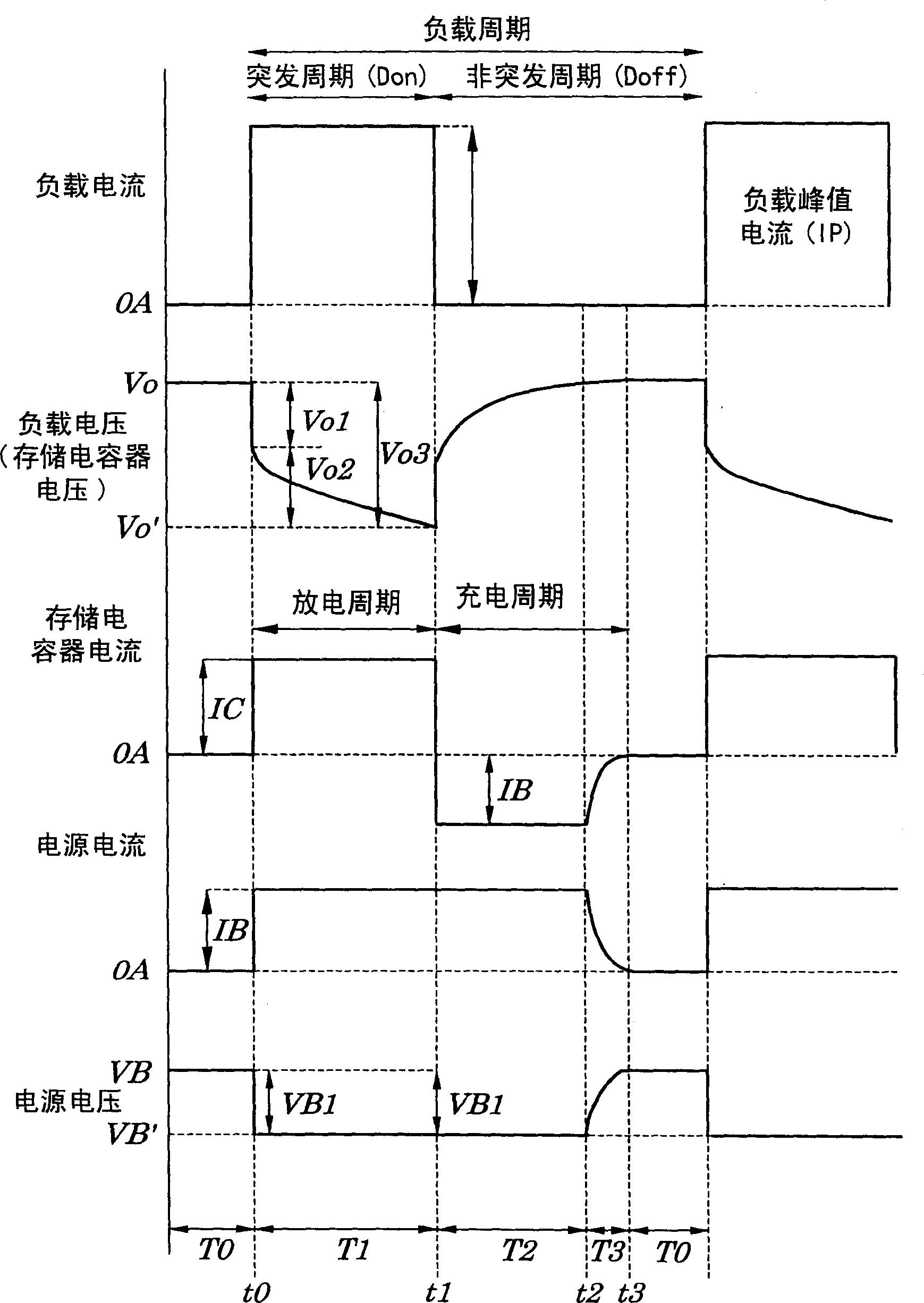
[0068] figure 2 A specific configuration circuit diagram of the power supply circuit of the first embodiment is shown. image 3 is a timing chart for illustrating the operation of the power supply circuit of the first embodiment. Figure 4 is a diagram for explaining the effect of prolonging the battery life in the power supply circuit of the first embodiment.

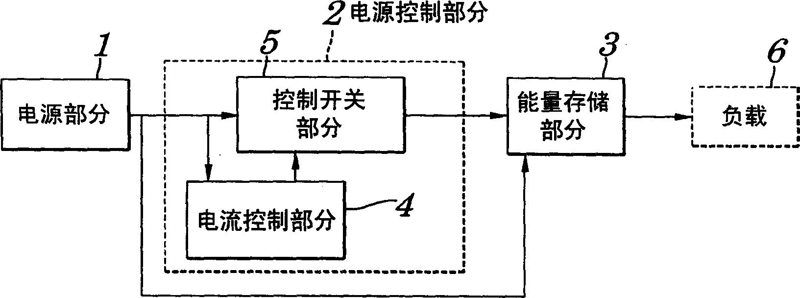
[0069] Such as figure 2 As shown, the power supply circuit of the first embodiment mainly includes a power supply part 11 , a power supply control part 12 and an energy storage part 13 . The power control section 12 is composed of a current control section 14 and a control switch section 15 .

[0070] The power supply unit 11 is a direct current power supply using a chemical battery, and is composed of a battery holder capable of accommodating a secondary battery 111 or a primary battery 11...

no. 2 example

[0116] Figure 6 A specific configuration circuit diagram of a power supply circuit according to a second embodiment of the present invention is shown.

[0117] Such as Figure 6 As shown, the power supply circuit of this embodiment mainly includes a power supply part 11 , a power supply control part 12A and an energy storage part 13 . Wherein, the power supply part 11 and the energy storage part 13 and figure 2 The same applies to the power supply circuit shown with the first basic configuration.

[0118] The power supply control section 12A is made up of the following parts: a current control section 14A adapted to generate a control signal to control the current output from the power supply section 11; Control current, and suitable for controlling output voltage to load 16. The current control section 14A is constituted by a voltage detection circuit 143 having a plurality of detectors 141 for comparing the voltage output from the power supply section 11 with a plurali...

no. 4 example

[0147] The configuration of a power supply circuit having a power supply section different from that of the second and third embodiments of the present invention will be described below. Also, in this case, since the configurations of the power supply control section and the energy storage section may be ones employed in the above-described embodiments, descriptions thereof are omitted.

[0148] Figure 8 A configuration circuit diagram of a power supply section in a power supply circuit according to a fourth embodiment of the present invention is shown. The power supply section 11A in the power supply circuit of the present embodiment is a DC power supply using a chemical battery, and it is constituted by a battery holder that can accommodate a secondary battery 111 or a primary battery 112 . The power supply section 11A includes a secondary battery charging circuit 113 , a capacitor 115 and a charging prevention switch 117 .

[0149] The secondary battery 111 has an intern...


PUM


Abstract

A power circuit is provided which has a small peak value of a current from a power source even in the case of a load in which a load current repeats periodically and alternately a burst flow in a burst period and a non-burst flow in a non-burst period. The above power circuit is provided with a power source section, a power controlling section, and an energy storing section having a storage capacitor being connected to an output terminal, a current controlling circuit to control values of detecting resistors according to a result of detection of a voltage input from a power source section and a control switching device having a field effect transistor switch being connected between input and output terminals and a circuit made up of a capacitor in which a flowing period of an output current is controlled by exerting the field effect transistor switch according to a control signal being produced by detecting a change in an input power voltage using a voltage occurring at another terminal of the detecting resistor.

Description

technical field [0001] The present invention relates to a power supply circuit capable of generating a peak power supply current suitable for supplying loads with cyclically varying power consumption and capable of allowing the amount of current consumed to exceed the upper limit for a set period of time and a method of controlling the power supply circuit. limit. [0002] This application claims priority from Japanese Patent Application No. 2002-045219 filed on February 21, 2002, which is incorporated herein by reference. Background technique [0003] In recent years, as terminals of portable devices have become multifunctional to connect to or access the Internet, distribute moving pictures, and the like, transmission speeds and data communication volumes tend to increase. Moreover, in essence, the terminals of these portable devices are not only made multifunctional, but also made smaller and lighter from the viewpoint of ease of use. [0004] On the other hand, as term...

Claims


Application Information

Patent Timeline
Patent Type & Authority Applications(China)
IPC IPC(8): H02J7/00H02J7/34H02M3/155
CPCH02J7/345H02M3/07
Inventor 佐佐木浩
Owner TOKIN CORP
Why Eureka
Try Eureka