
Method for measuring motor constant of induction motor

A technology of induction motor and electric motor, which is applied in the estimation/correction of motor parameters, motor generator testing, motor control in four quadrants, etc. question

Inactive Publication Date: 2003-09-10
YASKAWA DENKI KK
View PDF1 Cites 13 Cited by
  • Summary
  • Abstract
  • Description
  • Claims
  • Application Information

AI Technical Summary

Problems solved by technology

In addition, in the no-load current test, the induction motor needs to be operated alone. When the load is already applied, it is necessary to temporarily cut off the load to make the operation of the motor alone, which will lead to a decrease in efficiency.
[0004] In addition, in Conventional Example 2, since it is necessary to apply a single-phase alternating current and use Fourier series expansion to obtain the constant of the motor, the software becomes complicated, the processing time of the software becomes longer, and the software requires a large amount of memory. capacity problem

Method used


Image

  • Method for measuring motor constant of induction motor
  • Method for measuring motor constant of induction motor
  • Method for measuring motor constant of induction motor

Examples


Embodiment Construction

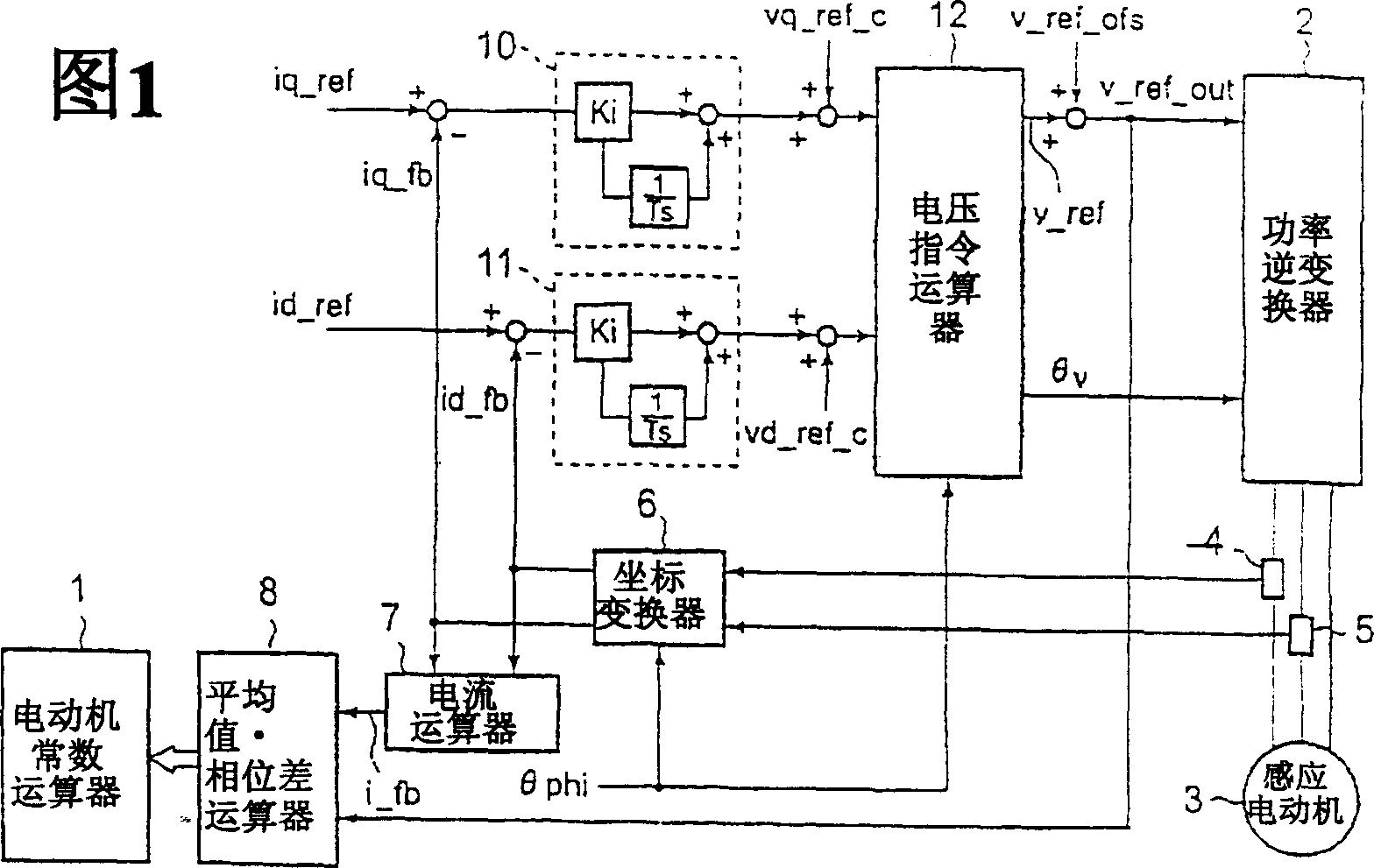
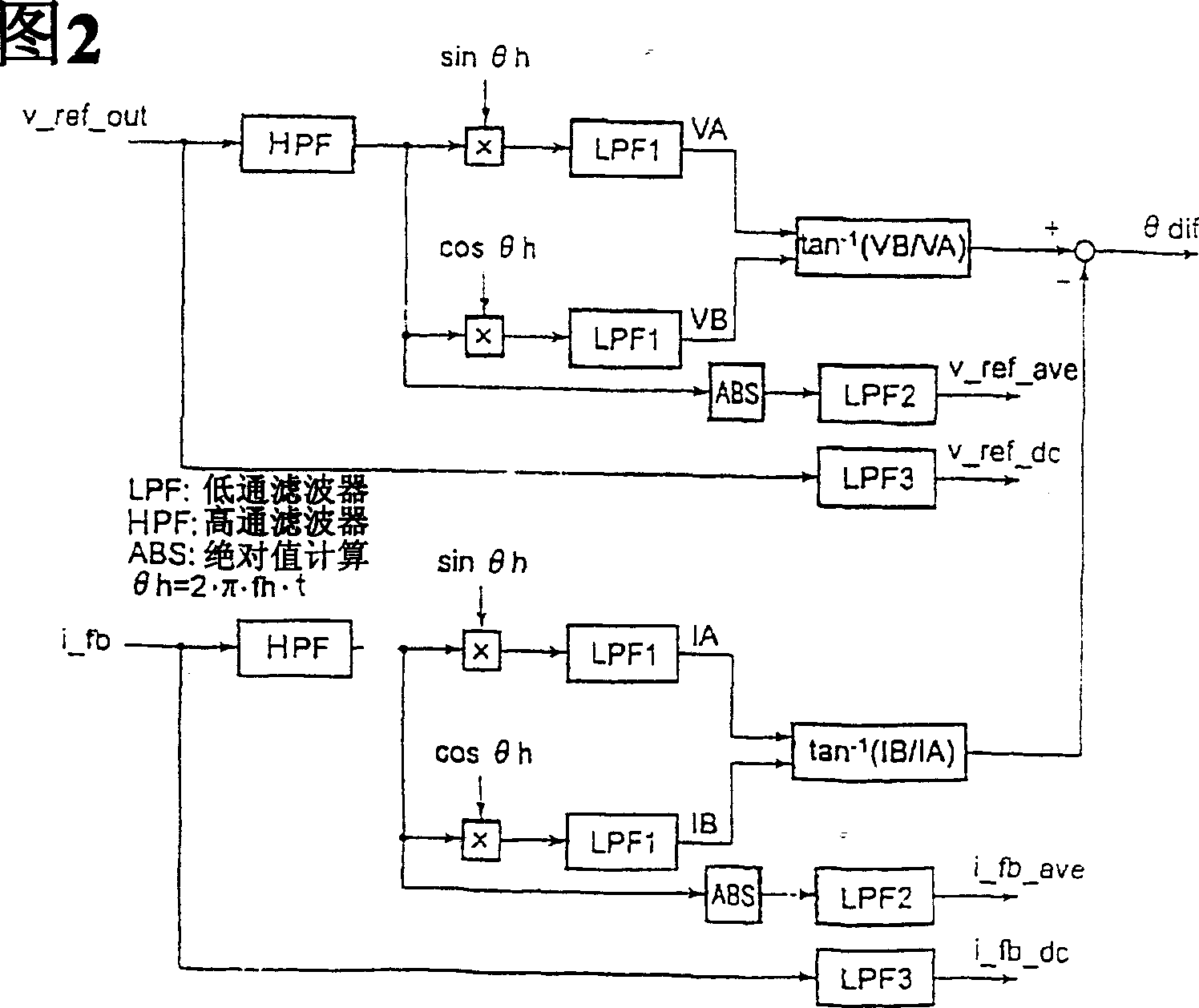
[0052] Fig. 1 is a block diagram showing the configuration of an embodiment of an induction motor control device according to the present invention. The proportional-integral controller 10 is used to control the deviation between the q-axis current command iq_ref and the q-axis current detection value iq_fb to make it zero, and add the q-axis auxiliary voltage command vq_ref_c to the output of the proportional-integral controller 10 to generate the q-axis voltage command vq_ref. Similarly, the proportional-integral controller 11 is used to control the deviation between the d-axis current command id_ref and the d-axis current detection value id_fb to make it zero, and add the d-axis auxiliary voltage command vd_ref_c to the output of the proportional-integral controller 11 to generate d Shaft voltage command vd_ref. The proportional gain of the proportional-integral controller is expressed as Ki, and the integral gain is expressed as (1 / T). The voltage command calculator 12 i...


PUM


Abstract

A method of measuring a motor constant is provided in a vector control apparatus for an induction motor. A voltage output phase [theta]v is set at an previously set arbitrary phase. Prior to applying a current, a current command is fed to operate the vector control apparatus with a proportional-plus-integral controller being set operative. After conduction for a predetermined time, the gain of the proportional-plus-integral controller is set to zero to maintain an integrated value constant and accordingly fix a voltage command value. In this state, a current command value and a detected current value are measured. k is measured at two levels of current, and a primary resistance value (or a line-to-line resistance value) is derived from the slope.

Description

technical field [0001] The invention relates to a method for measuring the motor constant of an induction motor. Background technique [0002] As the prior art, the method of obtaining the motor constant by performing the winding resistance measurement shown in JEC-37, the stall test, and the no-load test is written into the control software of the inverter (existing example 1); in addition , as a method of tuning the induction motor constants when the induction motor is in a stopped state is disclosed in JP-A-7-55899 (Conventional Example 2). In this method, a single-phase alternating current is supplied to an induction motor, and a d-axis current detection value or a q-axis current detection value is subjected to Fourier series expansion to obtain constants of the induction motor. Here, the d-q axis coordinates are rotational coordinates that rotate at the same speed as the rotating magnetic field of the motor. [0003] In the method shown in Conventional Example 1, duri...

Claims


Application Information

Patent Timeline
Patent Type & Authority Applications(China)
IPC IPC(8): G01R31/34H02P21/00H02P21/14H02P21/16H02P21/22H02P23/07H02P23/14H02P27/04
CPCG01R31/343G01R31/34
Inventor 藤井秋一井浦英昭井手耕三行平义昭
Owner YASKAWA DENKI KK
Learn More