Medium antenna of high frequency radio communication equipment

A technology of wireless communication equipment and dielectric antenna, which is applied in the field of antenna, can solve the problems of space consumption, increase of production cost, impedance mismatch between antenna line and feeder end, and achieve the effect of improving performance

Inactive Publication Date: 2003-09-17
NGK SPARK PLUG CO LTD
View PDF1 Cites 3 Cited by
  • Summary
  • Abstract
  • Description
  • Claims
  • Application Information

AI Technical Summary

Problems solved by technology

Also, although it is known to insert a matching circuit between the line on the substrate side of the element package and the antenna line, adding such a matching circuit tends to increase the production cost and consume too much space, which of course runs counter to the miniaturization requirement
[0005] There are various factors that can cause an impedance mismatch between the antenna line and the end portion of the feeder
Impedance mismatch issues are most likely to occur when, for example, the antenna line width is different than the feed strip line width for signal transmission due to design constraints, especially when the antenna line width is smaller than the feed strip line width due to antenna miniaturization

Method used


Image

  • Medium antenna of high frequency radio communication equipment
  • Medium antenna of high frequency radio communication equipment
  • Medium antenna of high frequency radio communication equipment

Examples


Embodiment Construction

[0029] Reference will now be made to the accompanying drawings, and in particular to figure 1 , an embodiment according to the first aspect of the present invention will be described.

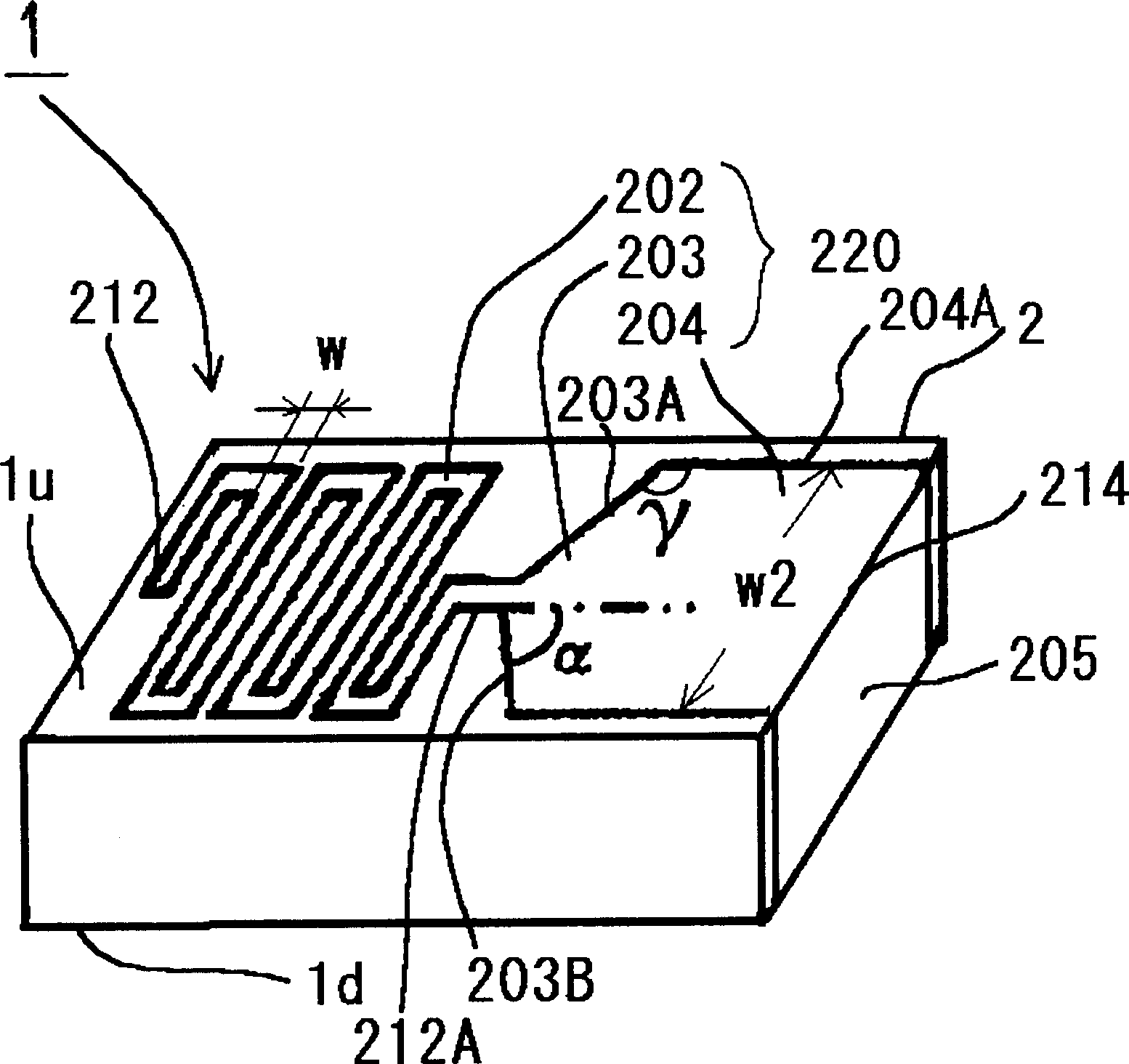
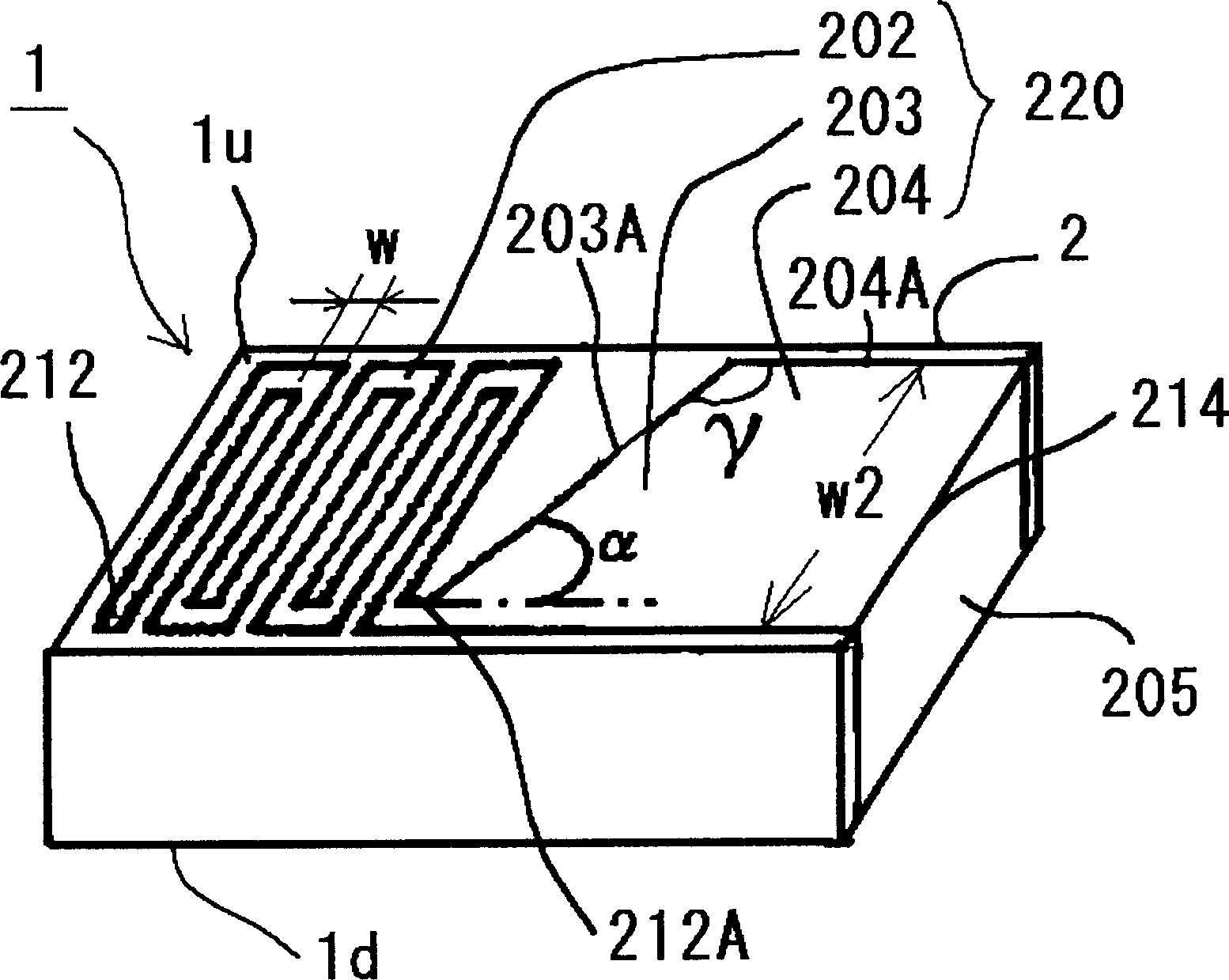
[0030] refer to figure 1 , the dielectric antenna 1 includes: a dielectric substrate 2, which is typically made of alumina ceramics, and has a rectangular solid shape; Baked on 1u. The lead portion 220 includes: a conductive meander layer or element 202 , a conductive feeder layer or element 204 , and a conductive tapered layer or element 203 . The tapered layer 203 connects one end of the meander line layer 202 to the feeder layer 204 and has an edge 203A which is inclined in the direction towards the meander line layer 202 with respect to an adjoining edge 204A of the feeder layer 204, i.e. 204A is sloped at an angle. The angle γ formed between these two edges is 110° to 175°, more preferably 120° to 170°. The other end 212 of the meander line layer 202 is a non-electric end. The other ...


PUM

PropertyMeasurementUnit
Lengthaaaaaaaaaa
Widthaaaaaaaaaa

Abstract

The invention provides a dielectric antenna for high-frequency wireless communication equipment. The dielectric antenna includes a dielectric substrate and a conductive meander line layer formed on the dielectric substrate. A conductive feeder layer is also formed on the dielectric substrate, and the line width of the conductive feeder layer is greater than that of the meander line layer. The conductive tapered layer connects the conductive meander line layer to the conductive feed line layer. The edge of the conductive tapered layer is inclined at an angle to the adjacent edge of the conductive feeder layer in the direction towards the conductive meander layer.

Description

field of invention [0001] The present invention relates to an antenna for wireless communication, and more particularly to a dielectric antenna for high-frequency wireless communication having a so-called meander structure formed on a dielectric substrate. Background of the invention [0002] The antenna is an essential component in wireless communication, but relatively speaking, the antenna has the disadvantage of consuming or occupying a large amount of space. In order to reduce the size of the antenna, a known antenna structure uses a dielectric material and forms an antenna line on or inside the dielectric material. An example of an antenna according to this prior art is described in Japanese Patent Publication No. 13126 / 1998. In order to suppress or reduce temperature rise (heat generation) caused by power loss of the radiation electrode, and to provide an antenna with reduced wavelength fluctuation, the antenna has a configuration shown in FIG. 13 . 13, the antenna ...

Claims


Application Information

Patent Timeline
IPC IPC(8): H01Q1/38
Inventor 杉本典康金森孝司中田大介若松进高田俊克
Owner NGK SPARK PLUG CO LTD
Why Eureka
Try Eureka