Cross head of crank rod type piston compressor

A crank connecting rod and cross head technology, which is applied in the cross head field of crank connecting rod piston compressors, can solve the problems affecting the overall size of the whole machine, large size, high production cost, etc. It is required to reduce and eliminate the effect of bearing shear force

Inactive Publication Date: 2003-10-01
XI AN JIAOTONG UNIV
View PDF0 Cites 16 Cited by
  • Summary
  • Abstract
  • Description
  • Claims
  • Application Information

AI Technical Summary

Problems solved by technology

[0004] 1. The piston force is first transmitted to the crosshead by the piston rod, and then transmitted to the connecting rod by the crosshead pin seat through the crosshead pin. Therefore, the crosshead needs to bear a large value of piston force, which leads to the crosshead designed according to the strength requirements. The body is extremely bulky, especially in large compressors, which makes installation and maintenance extremely inconvenient
[0005] 2. The huge piston force acts on the crosshead, resulting in a decrease in the reliability of the crosshead components
[0006] 3. The structure of the crosshead is complex, difficult to manufacture and process, and the production cost is high
[0007] 4. The piston rod is connected with the boss at the front of the crosshead body, and the front part of the boss is a crosshead nut for fastening the piston rod, which leads to a large size of the part in the axial direction of the compressor cylinder, which in turn affects the overall size of the machine
[0008] 5. The piston pin needs to be positioned axially
[0014] These defects of the above-mentioned traditional structure crosshead and the new structure crosshead lead to their unsatisfactory use effect

Method used


Image

  • Cross head of crank rod type piston compressor
  • Cross head of crank rod type piston compressor
  • Cross head of crank rod type piston compressor

Examples


Embodiment Construction

[0027] Below in conjunction with accompanying drawing and embodiment the content of the present invention will be further described:

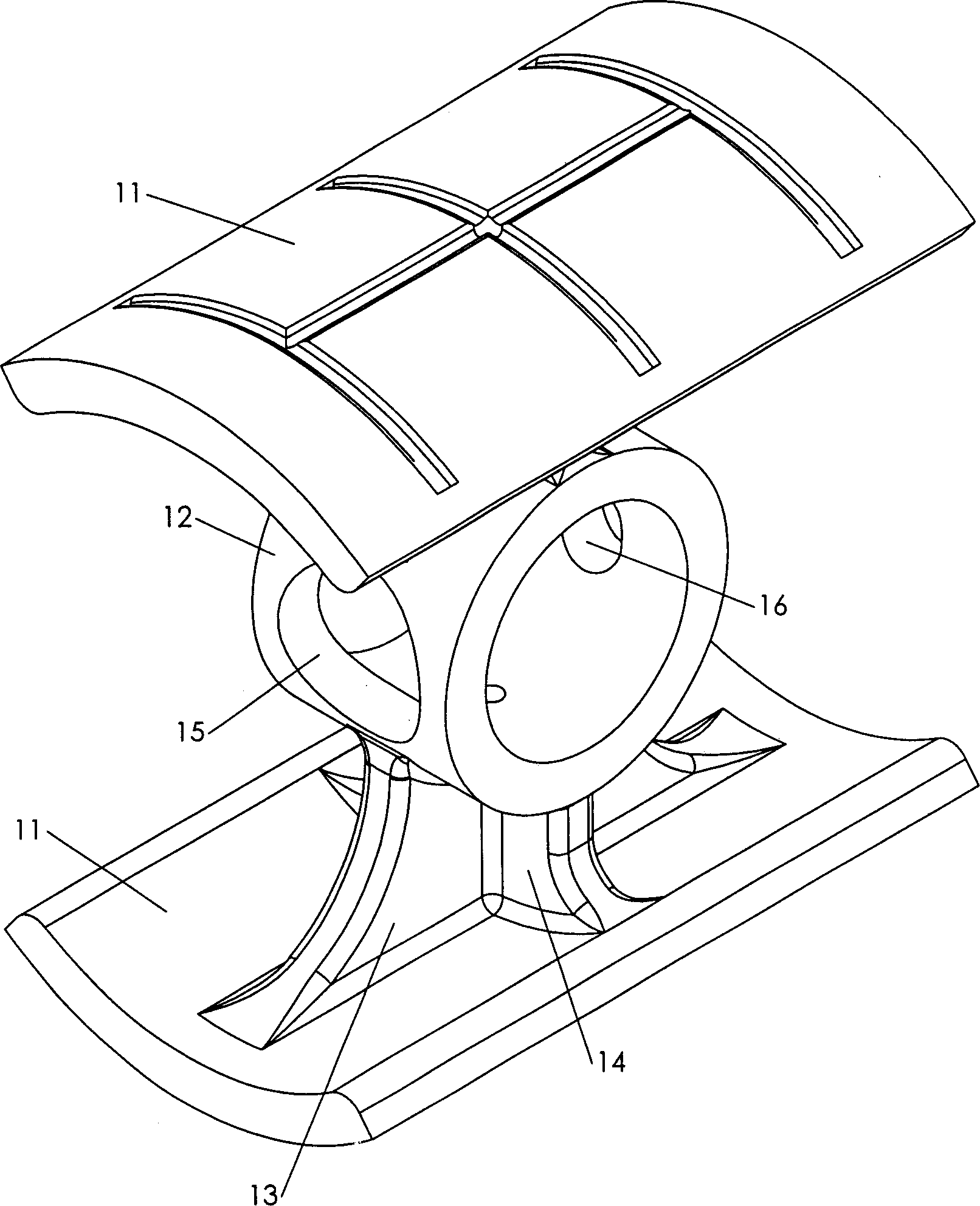
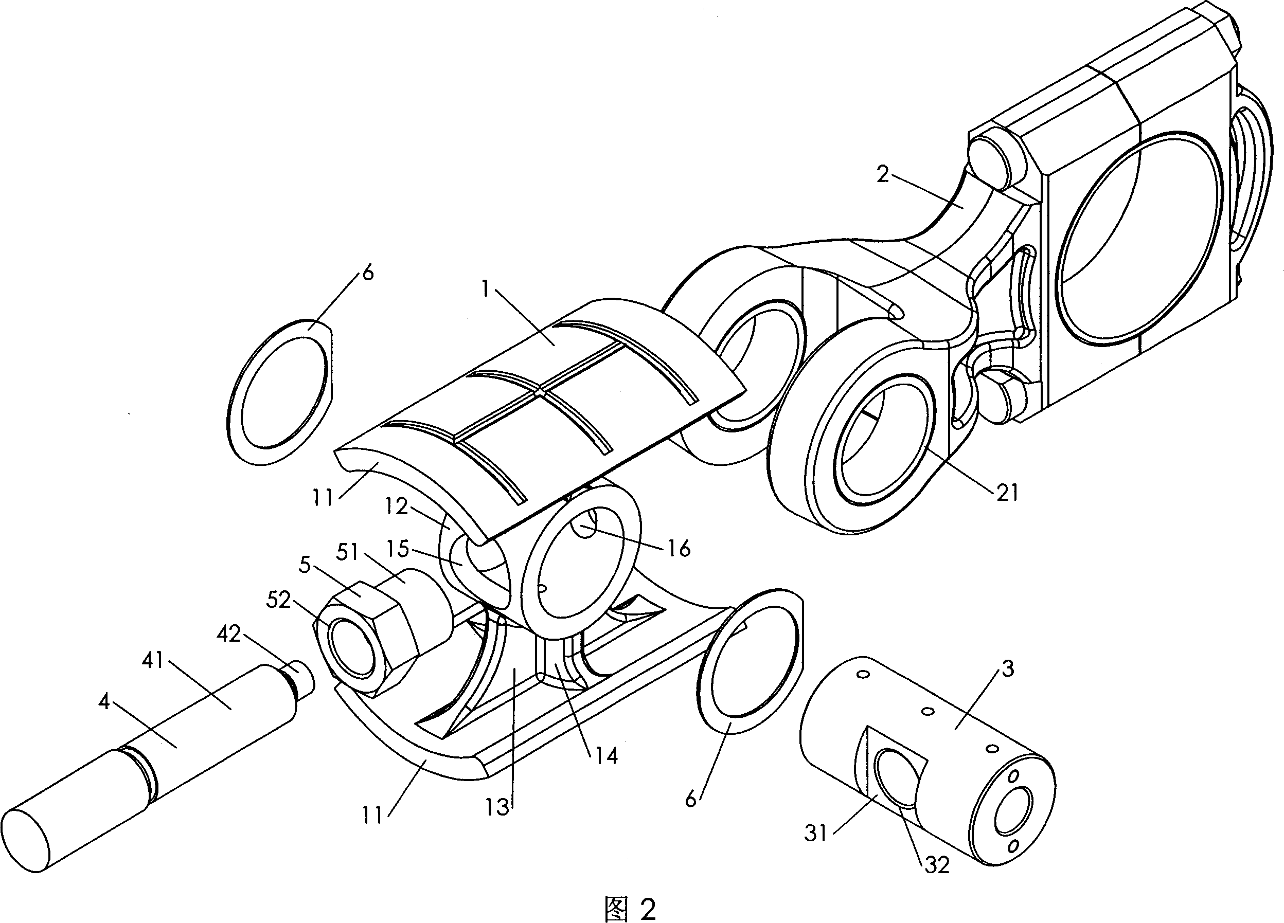
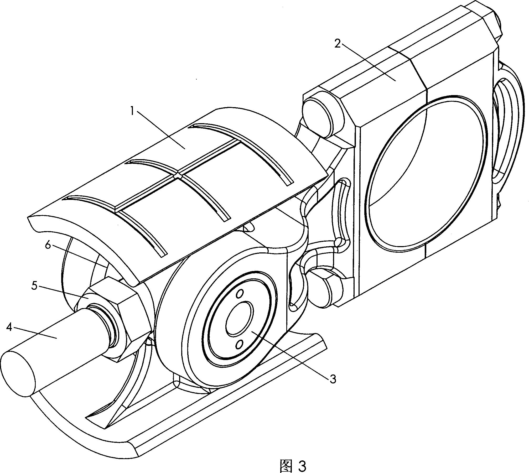
[0028] figure 1 ~Among Fig. 3: 1-crosshead body, 2-connecting rod, 3-crosshead pin, 4-piston rod, 5-crosshead nut, 6-friction-reducing locating ring.

[0029] refer to figure 1 As shown, the crosshead body 1 proposed by the present invention includes: two arc-shaped sliding shoes 11 that share a cylindrical surface and are symmetrical to the center of the cylindrical axis, and a pin located in the middle of the length and width directions of the sliding shoe. Hole seat 12, two vertical and horizontal ribs 13 and 14 that connect said pin hole seat 12 with said arc-shaped sliding shoes 11. The two arc-shaped sliding shoes 11 are symmetrical to the axis of the pin hole seat 12, and a larger circular through hole 15 and a smaller oblong hole are respectively opened on the two side walls of the pin hole seat 12. Shaped hole 16, two holes are all ...


PUM


Abstract

A cross-linked coupling for crank-connecting rod piston compressor is disclosed. A short cylindrical cross pin with screwed through hole perpendiculart to its basic line is used to pivot a cross bodyhaving a single pin hole seat to the connecting rod with smaller fork end. Said pin hole seat has two through holes coaxial with the sliding cylindrical surface. The piston rod whose end has externalscrew passes through the bigger hole on pin hole seat and then is turned into the screwed through hole on cross pin. A short cylinder at the end is inserted in another hole to locate the cross-linkedcoupling. A cross nut has a cylindrical end, which is also inserted said bigger hole to lock the piston rod to the cross-linked coupling.

Description

1. Technical field [0001] The invention relates to a crank connecting rod type piston compressor cross head, which is especially suitable for replacing other types of cross heads in any crank connecting rod type piston compressor with a cross head. 2. Background technology [0002] The crosshead is a transitional part that converts the rotary motion of the crankshaft into the reciprocating motion of the piston in the crank-connecting rod piston compressor. It is one of the most critical components in the piston compressor and directly affects the economy, reliability and maintainability of the compressor. sex. [0003] The crosshead part of the traditional structure includes a box-shaped crosshead body with two pin-hole seats, a connecting rod whose small head is sandwiched between the two pin-hole seats of the crosshead body, and the crosshead body and the small head of the connecting rod are hinged. cylindrical or conical crosshead pins, hexagonal crosshead nuts and pisto...

Claims


Application Information

Patent Timeline
Patent Type & Authority Applications(China)
IPC IPC(8): F01B9/00F04B27/08F16C5/00
Inventor 高秀峰冯诗愚郁永章
Owner XI AN JIAOTONG UNIV
Why Eureka
Try Eureka