

Fly frame with multiple electric motors controlled by microcomputers
A microcomputer-controlled, multi-motor technology, applied to spinning machines, continuous winding spinning machines, textiles and papermaking, etc., can solve the problems of low roving quality, cumbersome debugging and maintenance, and high manufacturing costs, and achieve roving quality High level, low manufacturing difficulty, good real-time effect
- Summary
- Abstract
- Description
- Claims
- Application Information
AI Technical Summary
Problems solved by technology
Method used
Image

Examples
Embodiment Construction
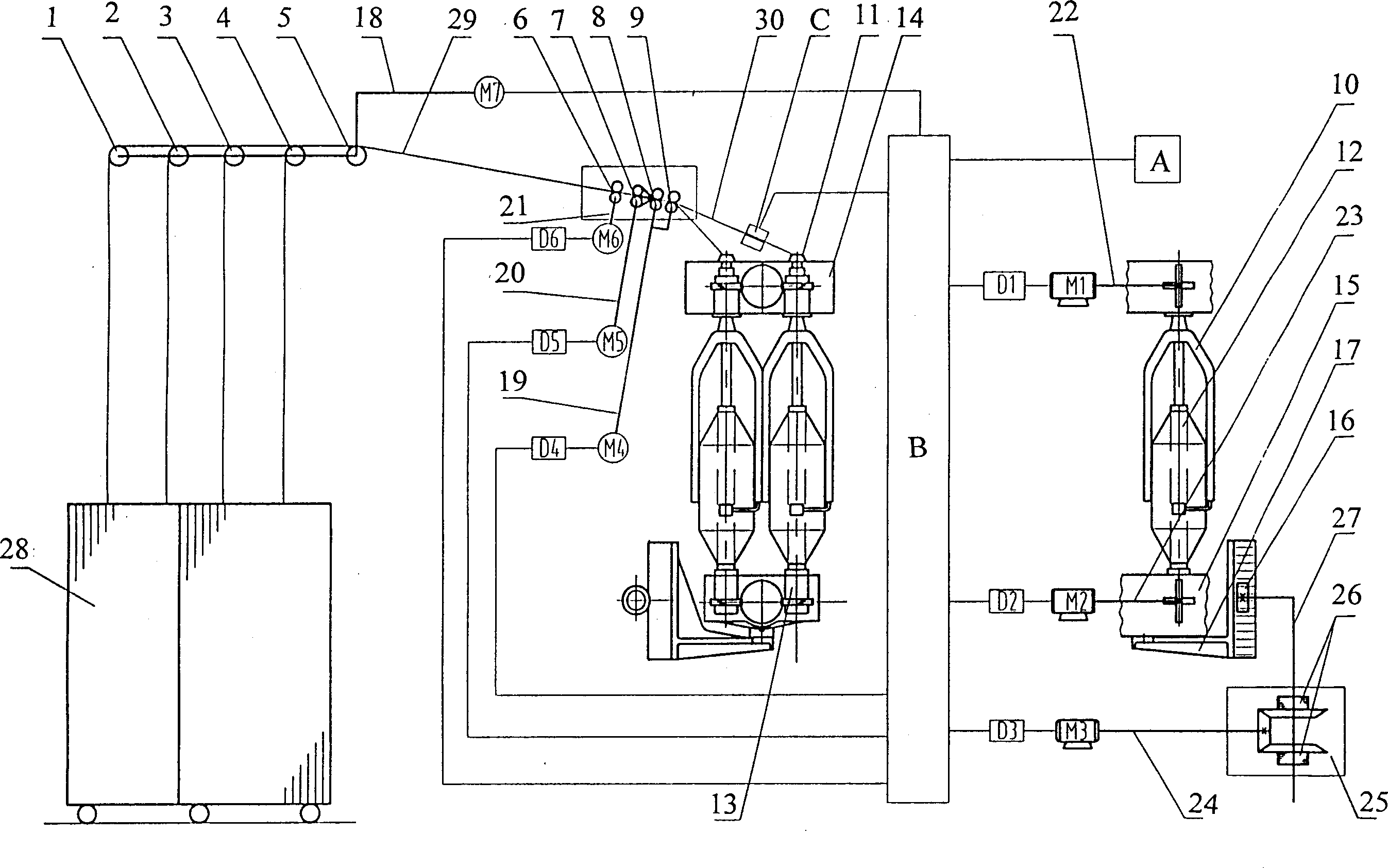
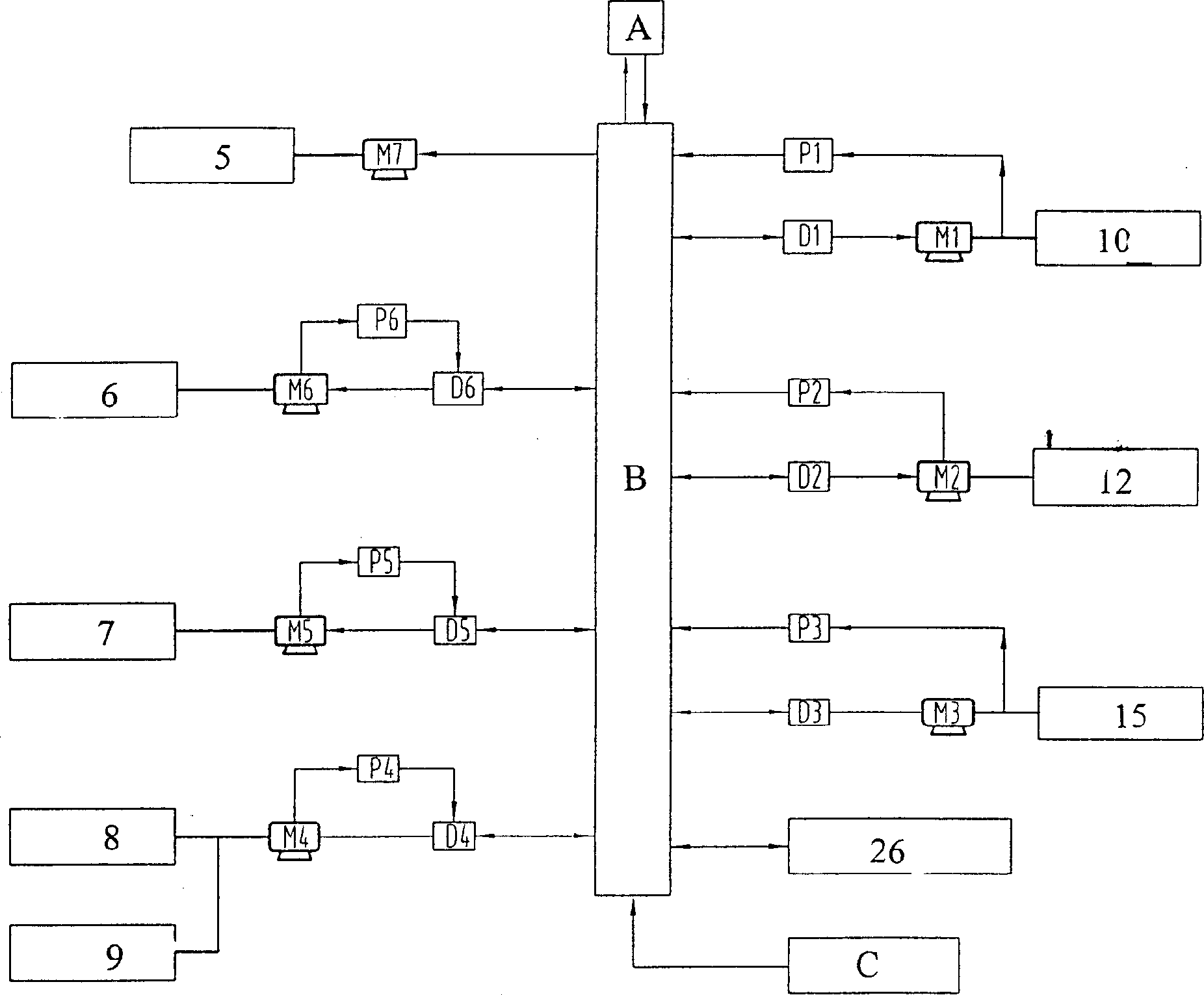
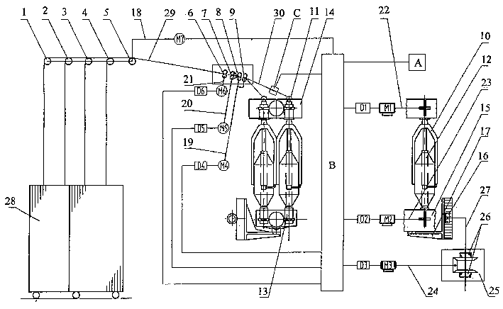
[0016] The present invention is described in more detail by specific examples below.
[0017] As shown in the figure, 1, 2, 3, 4, 5 are guide rollers, 6 is the rear roller, 7 is the third roller, 8 is the second roller, 9 is the front roller, 10 is the flyer, 11 is the false twister, 12 is the bobbin tube, 13 is the bobbin gear, 14 is the upper dragon rib, 15 is the lower dragon rib, 16 is the lifting gear, 17 is the lifting rack bracket, 18 is the feeding transmission section, 19, 20, 21 are drafting Transmission section, 22 is the twisting transmission section, 23 is the winding transmission section, 24 is the lifting transmission section, 25 is the reversing gear box, 26 is the clutch, 27 is the gear box transmission section, 28 is the sliver barrel, 29 is the cotton 30 is the roving sliver, M1 is the twisting motor, M2 is the winding motor, M3 is the lifting motor, M4, M5, M6 is the drafting motor, M7 is the guide motor, A is the parameter instrument, B is the main control...
PUM
 Abstract
Description
Claims
Application Information