Cooling medium engine apparatus

A technology of engines and refrigerants, applied in the direction of steam engine devices, machines/engines, mechanical equipment, etc., can solve problems such as reuse, excessive heat, and pollute the environment, so as to prevent heat waste, solve environmental pollution, and achieve great social and economic benefits. Effect

Inactive Publication Date: 2003-10-15
于泷
View PDF0 Cites 2 Cited by
  • Summary
  • Abstract
  • Description
  • Claims
  • Application Information

AI Technical Summary

Problems solved by technology

[0002] Most of the air-conditioning systems currently in use use refrigerants to absorb and release heat, which releases a lot of heat, w

Method used


Image

  • Cooling medium engine apparatus
  • Cooling medium engine apparatus
  • Cooling medium engine apparatus

Examples


specific Embodiment

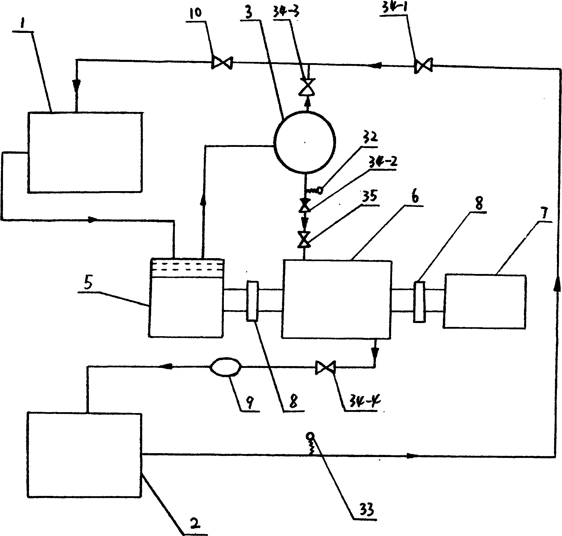
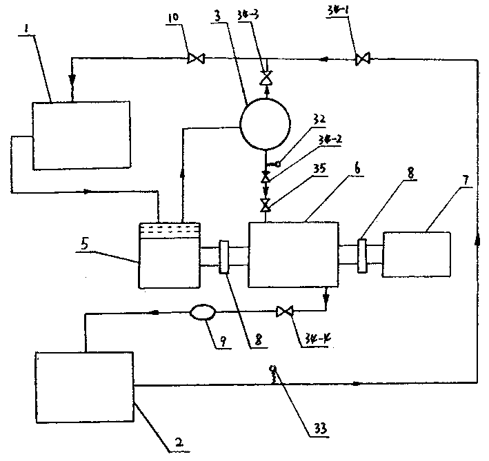
[0017] Such as figure 1 As shown, each device constitutes a closed loop system. According to the requirements of ordinary refrigeration technology, press and evacuate. After the refrigerant is quantitatively filled, the starter 7 starts, and the starter drives the refrigeration compressor 5 through the coupling 8, and the refrigeration compression Machine 5 starts to push the system to circulate, at the same time solenoid valves F1 (34-1) and F4 (34-4) are opened, solenoid valves F2 (34-2) and F3 (34-3) are closed, and the refrigerant liquid passes through solenoid valve F1 (34-4). -1), F4 (34-4) flows to the decompression device 10, after decompression, it flows into the evaporator 1 in a mist shape, and the refrigerant starts to absorb heat through the evaporator. The refrigerant enters the refrigeration compressor 5 from the initial subcooled low-pressure steam (fog), and is compressed by the refrigeration compressor 5 to become high-pressure superheated steam and sent to the ...


PUM


Abstract

The present invention relates to evaporation refrigerating system and is especially one kind of refrigerant engine plant for evaporation refrigerating system. Between the refrigerating compressor and heat radiator, there are successively connected energy accumulator, high pressure sensor D1, solenoid valve F2, regulating valve, refrigerant engine and solenoid valve F4; between the heat radiator and the decompressor there are successively connected low pressure sensor D2 and solenoid valve F1; and between the energy accumulator and the decompressor there is pipeline connected solenoid valve F3. The main shaft of the refrigerant engine is connected to the refrigerating compressor; and the refrigerant engine is one refrigerator driven turbine. The refrigerant engine plant has no environmental pollution and high heat efficiency.

Description

(1) Technical field [0001] The invention belongs to an evaporative refrigeration system, and particularly relates to a refrigerant engine device of an evaporative refrigeration system. (2) Background technology [0002] Most of the air-conditioning systems currently in use use refrigerants to absorb and release heat, which emits a lot of heat, which pollutes the environment and causes a waste of energy. How to reuse the generated heat is an urgent problem that needs to be solved. (3) Summary of the invention [0003] The purpose of the present invention is to utilize the heat generated in the evaporative refrigeration system for energy reuse. [0004] The purpose of the present invention is achieved in this way; [0005] The refrigerant engine device of the present invention is sequentially connected by an evaporator, a refrigeration compressor, a radiator, and a pressure reducing device into a closed circuit through a pipeline. Between the refrigeration compressor and the radia...

Claims


Application Information

Patent Timeline
IPC IPC(8): F01K11/02F24F12/00
Inventor 于泷
Owner 于泷
Why Eureka
Try Eureka