MOSFET and its manufacture

A metal oxide half-field and manufacturing method technology, applied in semiconductor/solid-state device manufacturing, semiconductor devices, electrical components, etc., can solve the problem that the anisotropic etching method is not easy to control, affects device performance, and deteriorates the surface properties of the channel region and other issues, to achieve the effect that the conditions of the production method are easy to control

Inactive Publication Date: 2003-11-05
WINBOND ELECTRONICS CORP
View PDF0 Cites 3 Cited by
  • Summary
  • Abstract
  • Description
  • Claims
  • Application Information

AI Technical Summary

Problems solved by technology

Second, when forming the spacer between the raised source and drain sidewalls of the FinFET, the spacer material (silicon nitride) on the sidewall of the fin-shaped silicon layer is removed by overetching, so the sidewall of the fin-shaped silicon layer Defects will be generated at the wall, that is, the surface properties of the channel region will deteriorate, which will affect the performance of the device
Third, in order to reduce the source and drain resistance of Fin

Method used


Image

  • MOSFET and its manufacture
  • MOSFET and its manufacture
  • MOSFET and its manufacture

Examples


Embodiment Construction

[0031] In order to make the above-mentioned objects, features and advantages of the present invention more obvious and easy to understand, a preferred embodiment is given below, and described in detail with the accompanying drawings as follows:

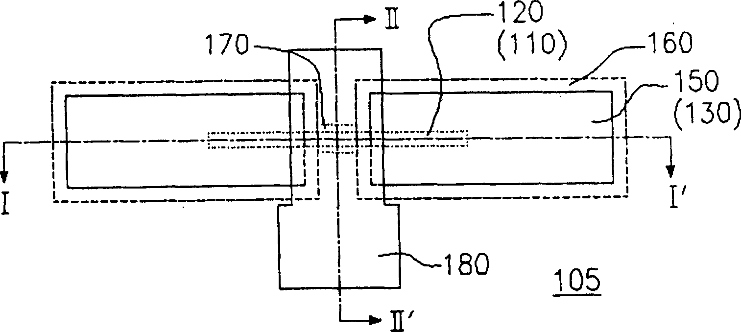
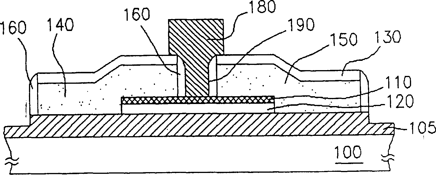
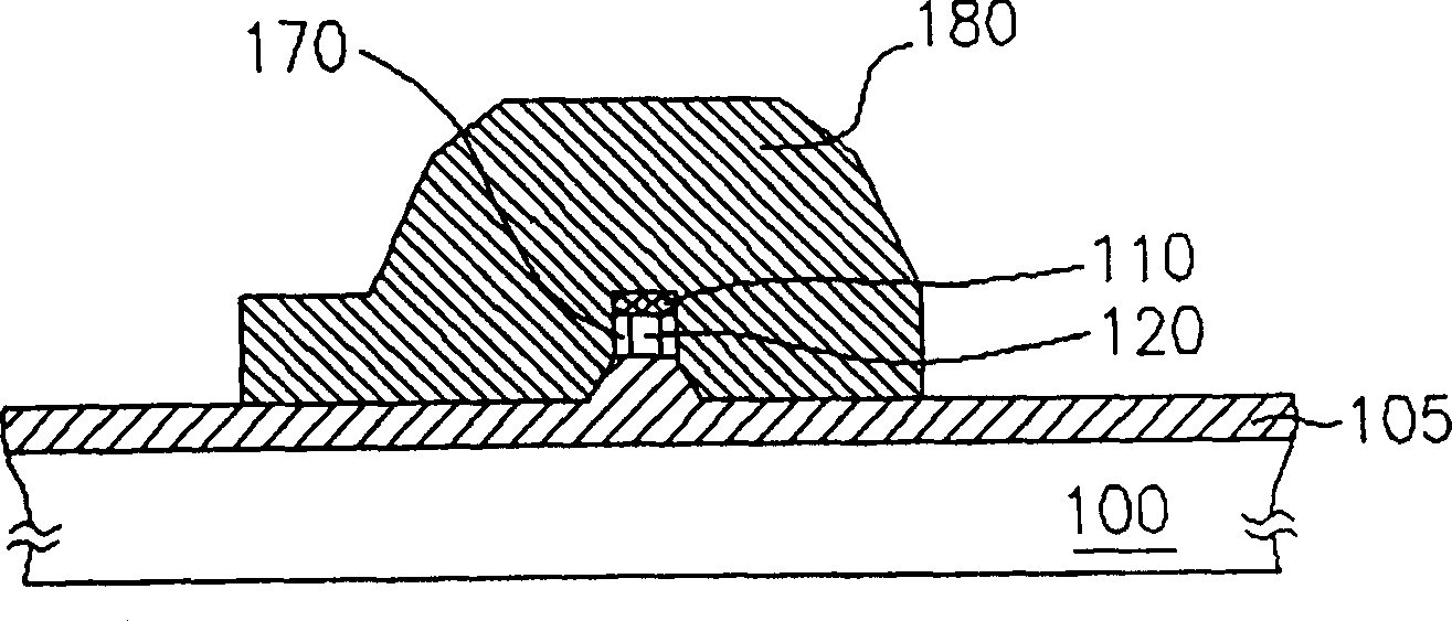
[0032] Please refer to figure 2 --9, is a sectional view of the manufacturing process of the MOSFET according to the preferred embodiment of the present invention; and please refer to Figure 2-1 , 5-1 , 6-1, 8-1, which are respectively figure 2 , 5 , 6, 8 top view, namely figure 2 , 5 , 6, and 8 are respectively Figure 2-1 , 5-1 , 6-1, 8-1 sectional view of the cutting line III-III'. in addition Figure 8-2 for Figure 8-1 Sectional view of cutting line IV-IV'.

[0033] Please refer to figure 2 , 2 -1, first provide a semiconductor substrate 200, such as a bulk silicon substrate, and then form a circular Shallow Trench Isolation (STI) and a shallow channel region (Channel Region) thereon. The material of the trench ...


PUM

PropertyMeasurementUnit
Thicknessaaaaaaaaaa

Abstract

The MOSFET features the channel inside the semiconductor substrate, the information channel area constituted with one doped semiconductor layer across the channel, the grid in and over the channel and around the information channel area with grid dielectric layer in between. The grid is separated from the side wall and bottom with one gapping wall and one insulating layer. The manufacture of the MOSFET includes following steps: forming channel filled with insulating layer on the substrate, eliminating the upper layer of the insulating layer, forming gapping wall on the side wall of channel,filling the channel with sacrificial layer; forming and defining one doped semiconductor layer on the substrate to form device area across the sacrificial layer; eliminating the sacrificial and forming grid dielectric layer on the surface of the device; forming conducting layer on the substrate filled into the channel and defining the conducting layer to form the grid; and forming source and drain on two sides of the grid.

Description

technical field [0001] The invention relates to a structure of a semiconductor device and a manufacturing method thereof, in particular to a metal-oxide-semiconductor field-effect transistor (MOSFET) and a manufacturing method thereof. Background technique [0002] With the shrinking of the line width of the metal oxide semiconductor (MOS) fabrication method, the leakage current between the source (Source) and the drain (Drain) away from the gate (Gate) increases accordingly. Although this leakage current can be reduced by a thin gate dielectric layer (Gate Dielectric), when the line width of the manufacturing method is reduced to less than 0.1μm, even a very thin gate dielectric layer cannot be reduced. leakage current. For this problem, Professor Chenming Hu of the University of California, Berkeley pointed out two solutions. One is to use a very thin semiconductor substrate to make MOSFETs, so that there is no longer any space in the substrate far away from the gate. Th...

Claims


Application Information

Patent Timeline
IPC IPC(8): H01L21/336H01L29/78
Inventor 张文岳
Owner WINBOND ELECTRONICS CORP
Why Eureka
Try Eureka