Wear-resistant coating and method fr applying it

A wear-resistant and coating technology, applied in the field of wear-resistant coatings, which can solve problems such as delamination

Inactive Publication Date: 2003-11-19
MITSUBISHI HEAVY IND LTD
View PDF0 Cites 18 Cited by
  • Summary
  • Abstract
  • Description
  • Claims
  • Application Information

AI Technical Summary

Problems solved by technology

Although brazing has the advantages of ease of handling and low cost, there are disadvantages in terms of oxidation resista

Method used


Image

  • Wear-resistant coating and method fr applying it
  • Wear-resistant coating and method fr applying it
  • Wear-resistant coating and method fr applying it

Examples


Embodiment Construction

[0021] Next, a first embodiment of the abrasion-resistant coating of the present invention will be described with reference to the drawings.

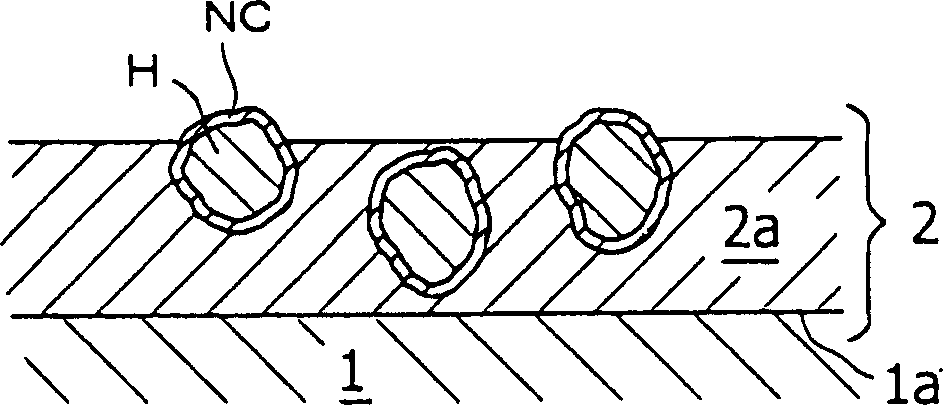
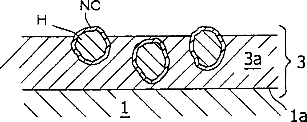
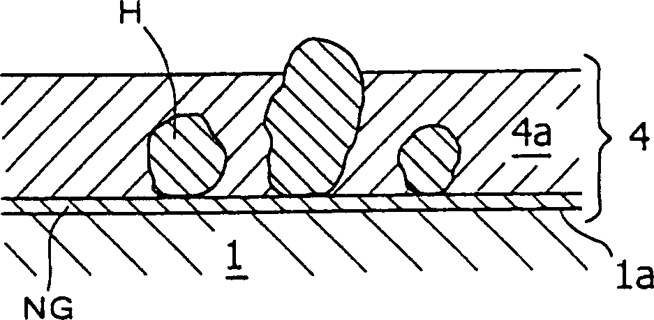
[0022] Such as figure 1 As shown, the wear-resistant coating is formed on the top of the matrix material 1 of the gas turbine blade, and the upper part (radial direction) of the paper surface. narrow gap. The thickness of the wear-resistant coating 2 at the tip 1a, for example, 300 µm, is formed as follows.

[0023] On the top 1a of the matrix material 1, hard particles H composed of CBN are fixed in the bond coat 2a by heating, melting and solidifying a mixture of solder and MCrAlY (M denotes metal elements such as Co and Ni). . The mixing ratio of solder, MCrAlY and CBN is about 60%:10%:30% (vol%).

[0024] The hard particles H contain Ni and Co-coated NCs to improve wettability relative to the solder, preferably some of the hard particles H are arranged so as to partially protrude from the surface of the bond coat to exhibit Fri...


PUM


Abstract

The present invention provides an abrasion-resistant coating which has high oxidation resistance and durability and can be applied easily at a low cost. The abrasion-resistant coating in accordance with the present invention is formed at the tip end of a base material forming a gas turbine blade. The abrasion-resistant coating at the tip end has a thickness of 300 microns. On the tip end, hard particles H consisting of CBN are fixed in a bond coating formed by heating, melting, and solidification of a mixture of a brazing filler metal and M-Cr-Al-Y (M designates a metal element such as Co and Ni). The hard particles H are Ni and Co coated to improve wettability relative to the brazing filler metal, and are arranged so that some of them are partially protruded from the surface of bond coating to exhibit the grindability.

Description

technical field [0001] The present invention relates to a wear-resistant coating applied on a metal matrix material for a blade tip portion of a gas turbine, an engine of a gas turbine, a compressor, etc., and a method of applying the wear-resistant coating. Background technique [0002] For example, the gap between the tip of the blade of the gas turbine and the sub-ring fixed on the inner peripheral surface of the blade installation part needs to be as small as possible in order to improve the efficiency of the gas turbine by limiting the shortcut of the gas to the downstream stage. [0003] However, if the gap is too small, at the initial stage of gas turbine start-up, due to the thermal expansion of the blade, the centrifugal of the rotating shaft, the vibration of the entire gas turbine, and the thermal deformation of the blade ring due to the long-term exposure of the gas turbine to high-temperature gas, etc., the blade's The tip portion is in contact with the blade su...

Claims


Application Information

Patent Timeline
IPC IPC(8): F01D5/28B23K1/20C23C6/00C23C10/18C23C24/10C23C26/00C23C26/02C23C28/02F01D5/20F04D29/02
CPCC23C28/44F05C2253/12F01D11/12F05D2300/611C23C28/023F05D2230/90C23C28/027C23C26/02C23C10/18C23C24/10C23C28/022C23C6/00C23C28/40
Inventor 大原稔妻鹿雅彦
Owner MITSUBISHI HEAVY IND LTD
Why Eureka
Try Eureka