
Direct connection pressure separating system for heat supply and iar conditioner

A separation system, direct connection technology, applied in heating systems, hot water central heating systems, household heating, etc., can solve problems such as reducing the overall advantages of the system, reducing thermal efficiency, affecting system operation, etc., to avoid serious corrosion of pipelines , the effect of increasing the cost and saving investment

Inactive Publication Date: 2003-11-26
沈阳市金鑫冷暖设备制造安装有限公司
View PDF0 Cites 2 Cited by
  • Summary
  • Abstract
  • Description
  • Claims
  • Application Information

AI Technical Summary

Problems solved by technology

[0005] Heat exchangers will lead to reduced thermal efficiency and inevitable temperature loss, especially in low-temperature water heating and air-conditioning systems, the disadvantages of using heat exchangers are particularly obvious, because after the low-temperature water is heat-exchanged, the temperature of the supply water is further reduced, and the user radiator The area increases, the heating effect deteriorates, the heat exchanger and the increased radiator increase the investment of the system; in the air conditioning system, the use of the heat exchanger will increase the temperature of the chilled water, in order to minimize the increase of the chilled water temperature, it must be increased The area of ​​the heat exchanger and the increase in temperature affect the effect of the air conditioner, and also increase the cost of the heat exchanger and terminal equipment
These well-known unfavorable factors lead to the decline of the function of the system, which greatly reduces the overall advantage of the system
[0006] Open overflow riser systems also have insurmountable disadvantages
First of all, because it is connected with the atmosphere, the system will inevitably enter a large amount of air, which will affect the operation of the system and corrode the pipeline; secondly, the open overflow riser system is a half-pipe flow, which is similar to the drainage riser, and there is a lot of noise. The kinetic energy of the water falling in the pipe will cause pressure fluctuations in the system

Method used

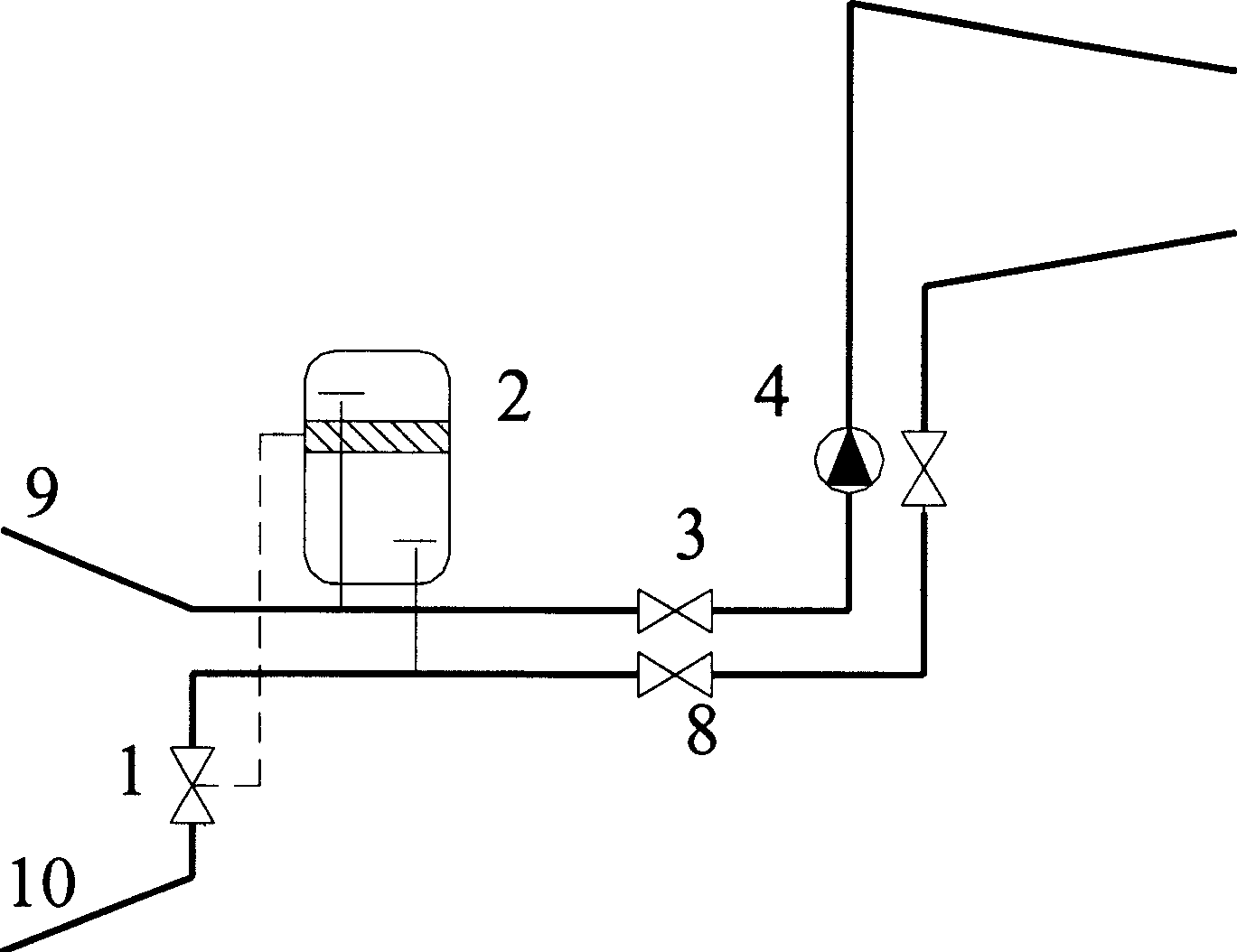
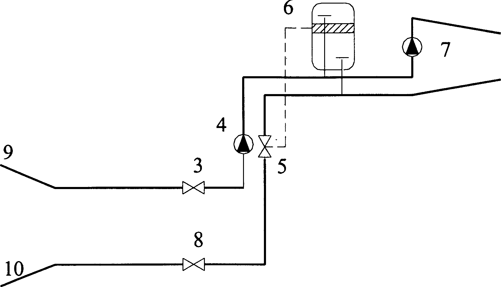
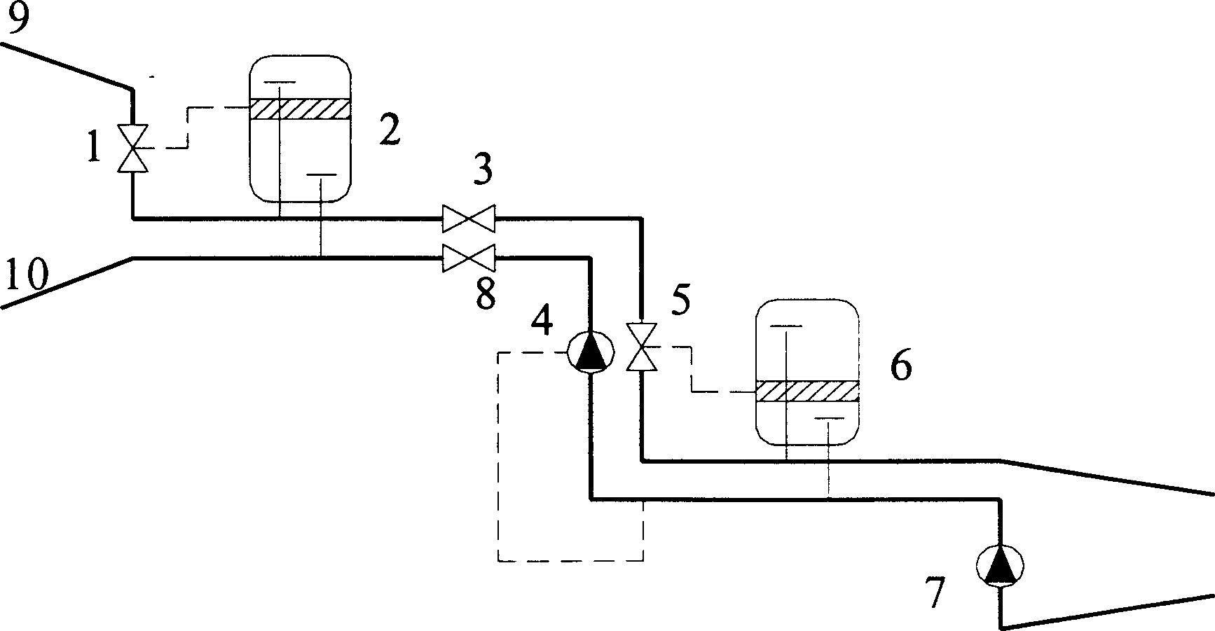

Image

  • Direct connection pressure separating system for heat supply and iar conditioner
  • Direct connection pressure separating system for heat supply and iar conditioner
  • Direct connection pressure separating system for heat supply and iar conditioner

Examples


Embodiment approach 1

[0041]In terms of system design, the present invention includes: shut-off valve V1, control tank A2, fast shut-off valve AVm3 interlocked with booster pump P4 installed on water supply pipe 9, shut-off valve V5, control tank B6, shut-off valve V7, partial system circulation pump P7, shut-off valve V9, shut-off valve V10, shut-off valve V8, control tank B6 temperature gradient control valve RVm5, shut-off valve V6, installed on the return pipe 10 and interlocked with the booster pump P4 The electromagnetic valve AVn8, the spring safety valve V15, the control tank A2 temperature gradient control valve RVn1, and the shut-off valve V2. The water supply of the system enters the local system from the water supply pipe through the shut-off valve V1, and is sequentially connected to the control tank A2 connected in parallel with the water supply pipe, the shut-off valve AVm3 interlocked with the booster pump P4, the shut-off valve V5, the booster pump P4, and the The water supply pipe...


PUM


Abstract

The present invention belongs to the field of heat supply and air conditioner equipment, and features that it contains control tank, boosting pump, control valve, check valve in water supply pipe andcheck valve in water return pipe. The control tank is connected to water supply pipe in the upper part and the water return pipe in lower part; the control valve is connected to the output end of the control unit; the control unit has its input connected to the control output of the control tank; and the two check valves are interlinked with the pump separately.

Description

Technical field [0001] The invention belongs to the field of heating and air-conditioning equipment, and particularly relates to a direct-connected pressure separation system for heating and air-conditioning that enables users with different operating pressures to be connected together on a hydraulic system. Background technique [0002] In heating and air conditioning systems, when a local system is connected to the main system, there is often a conflict that the operating pressures of the local system and the main system are different. For example, in a larger heat network, in order to maintain the normal operation of the heat network system, the operating pressure of the main heat network will exceed the pressure-bearing capacity of some user radiators, and direct connection will cause the radiator to burst. In addition, high-rise buildings or terrain The height difference between them will also create a contradiction between the operating pressure and the pressure bearin...

Claims


Application Information

Patent Timeline
Patent Type & Authority Applications(China)
IPC IPC(8): F24D3/10F24F13/02
Inventor 权太明张利华金武燮
Owner 沈阳市金鑫冷暖设备制造安装有限公司
Learn More