Method and device for connecting plastic material using high welding speed

A technology of plastic materials and transparent materials, which can be used in welding/welding/cutting items, welding equipment, laser welding equipment, etc., and can solve problems such as poor welding quality

Inactive Publication Date: 2003-12-10
LEISTER TECHNOLOGIES
View PDF0 Cites 18 Cited by
  • Summary
  • Abstract
  • Description
  • Claims
  • Application Information

AI Technical Summary

Problems solved by technology

However, this measure narrows the process window in which an individual adaptation of the process parameters is possible, so that the welding quality deteriorates considerably

Method used


Image

  • Method and device for connecting plastic material using high welding speed
  • Method and device for connecting plastic material using high welding speed
  • Method and device for connecting plastic material using high welding speed

Examples


Embodiment Construction

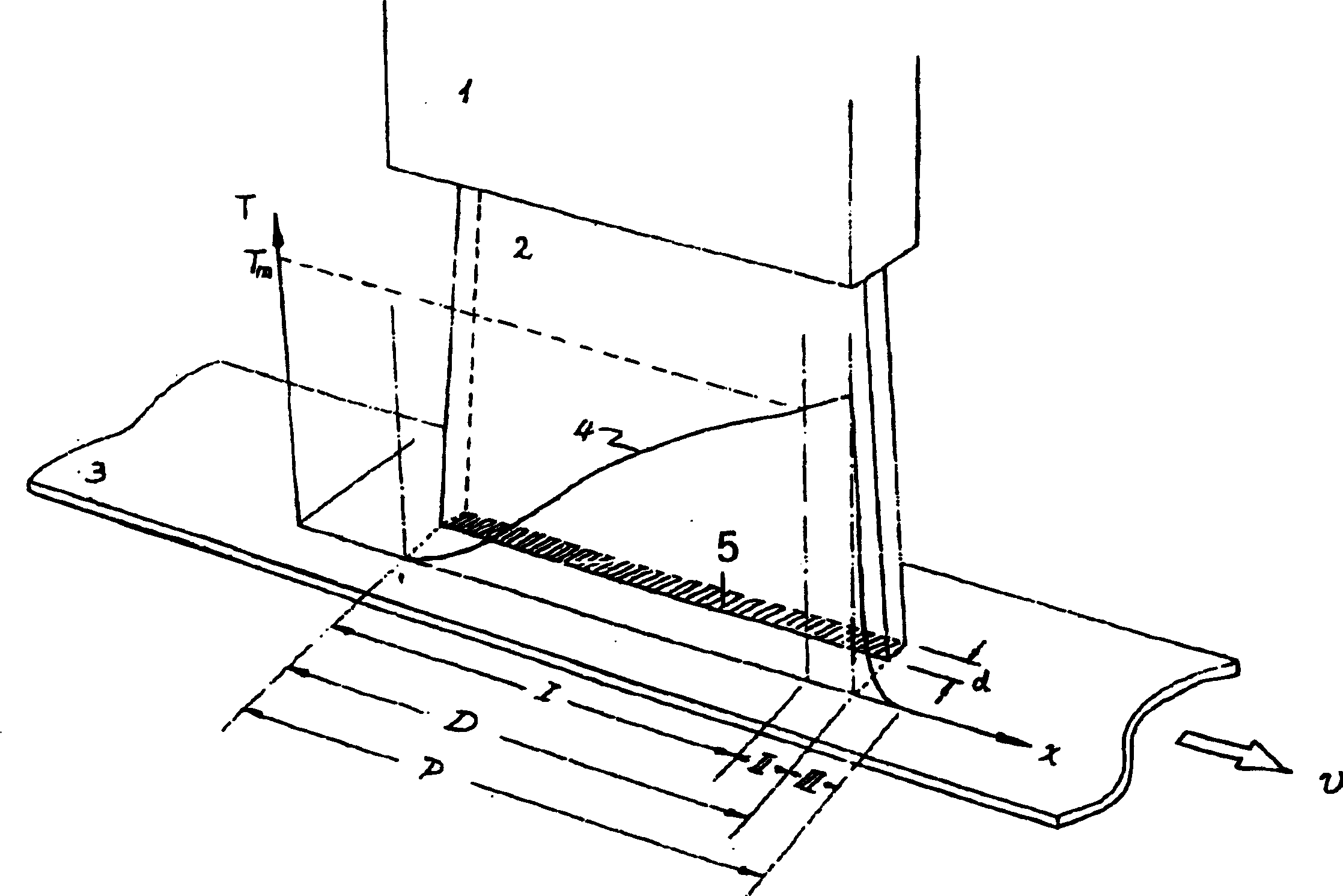
[0027] figure 1 Shown is a laser source 1 with a curtain-like collimated laser beam 2 which produces a linear irradiation field 5 on a plastic material 3 . The width d and length D of the irradiation field 5 can be influenced by a corresponding optical system. Plastic material 3 moves with velocity v in the direction of the arrow. Furthermore, the temperature curve 4 of the temperature T versus the distance x is shown in the figure. As shown in the figure and line 4, the temperature in the material continues to increase in the preheating zone I and finally reaches the melting temperature. From here melting zone II begins and ends in irradiation zone 5, the length of which is denoted by D. Thereafter the temperature starts to drop in cooling zone III. The overall duration of the welding process is denoted by P.

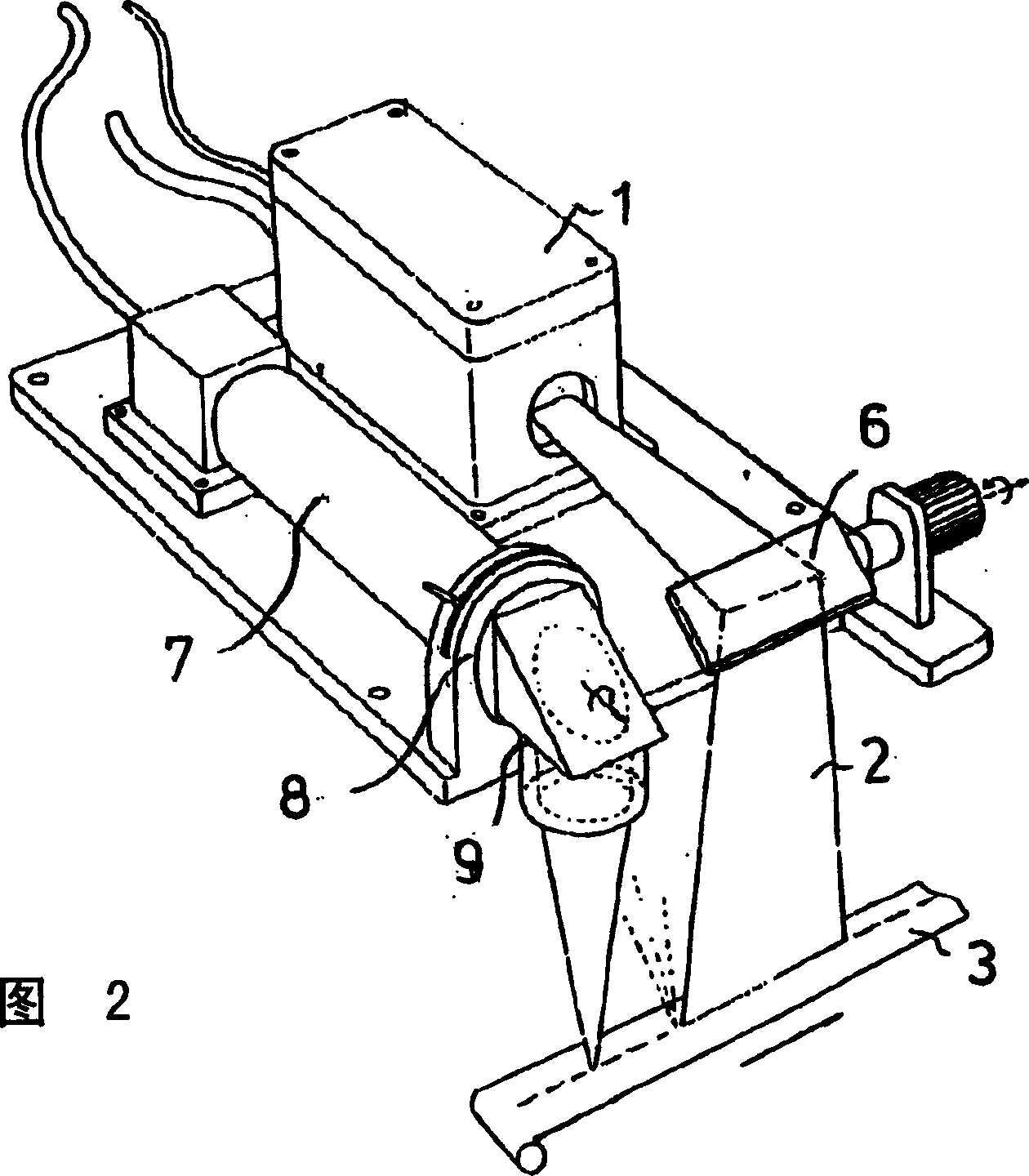
[0028] A structure is shown in Figure 2 to illustrate the principle, which shows figure 1 The curtain laser beam 2 of the laser beam is irradiated on a material ...


PUM


Abstract

Joining endless polymer materials (3) comprises shining upper material and contact surface between the upper and lower materials by using laser beam (2). The contact surface is transparent the laser beam. The lower material is opaque to the laser beam. The two materials are melted and joined to each other under pressure. Joining endless polymer materials (3) comprises shining upper material and contact surface between upper and lower materials by using laser beam (2). The contact surface is transparent the laser beam. The lower material is opaque to the laser beam. The two materials are melted and joined to each other under pressure. The laser beam and the materials to be joined are moved relative to each other to produce a welded seam running in the longitudinal direction at the contact surface. A process zone (P) is provided. The material is heated continuously to the melting temperature in a preheating zone (I) by using laser beams and is melted in a melting zone (II). An Independent claim is included for polymer materials joining apparatus comprising laser beam, material pressing device, and laser beam producing devices. The laser beam shines through the upper material because of transparency of the upper material and at the contact surface with the lower material. The lower material absorbs the laser beam. The laser beam heats the materials and melts them. The material pressing device joins endless materials. The endless materials are guided through two contra-rotating rollers (17, 18). The rollers press against each other. The first roller is made from a material transparent to a laser beam. The first roller is Tubular. The second roller is made from a material that can be deformed easily at the surface. The laser beam(s) producing devices produces laser beam(s) at the contact surface arranged in the first roller.

Description

technical field [0001] The invention relates to a method and a device for joining plastic materials with high welding speeds. Background technique [0002] It is known that plastic materials can be joined by means of a laser beam, wherein the upper material facing the laser beam is penetrated by the laser beam, the two materials are heated and linked together by pressure. Materials that are transparent to the laser beam can be optically black in the visible wavelength range. It is also known that for this purpose a linear laser beam needs to be generated, wherein during the welding process there is a relative movement between the material and the laser beam in order to produce the desired welding contour. [0003] A prerequisite for the welding process according to this penetration technology is the thermal reaction of the plastic to infrared radiation (IR-Bestrahlung). Plastic coated with an infrared-absorbing substance absorbs thermal energy from an infrared light sourc...

Claims


Application Information

Patent Timeline
Patent Type & Authority Applications(China)
IPC IPC(8): B23K26/00B23K26/06B23K26/073B23K26/08B23K26/18B23K26/20B23K26/24B23K26/32B29C65/00B29C65/16
CPCB29C66/83417B29C66/9221B29C65/1696B29C65/1635B29C65/1664B23K26/246B29C66/81268B23K26/0846B29C66/91216B29C66/91221B29C66/91931B23K26/0732B29C66/8167B29C66/9241B29C66/939B29C66/81457B23K2201/16B23K26/0661B29C65/16B29C66/0242B29K2909/08B29C66/83431B29C66/1122B29C65/1658B29C66/43B29K2833/12B29C66/83415B29C66/91411B23K26/18B23K26/009B29C66/8762B29C66/81267B29C66/9192B29C66/9161B29C66/83413B29C66/92211B29C66/919B29C66/934B29C66/961B29C66/73921B23K26/244B29K2995/0027B29C66/8122B29K2995/0025B23K2101/16Y10T156/1741
Inventor 陈杰伟A·尼德尔伯格
Owner LEISTER TECHNOLOGIES
Why Eureka
Try Eureka