Anode support tube type solid oxide fuel battery

A solid oxide and anode support technology, applied in solid electrolyte fuel cells, fuel cells, circuits, etc., can solve the problems of high cost, increased battery power density, low space utilization efficiency, etc., to increase the electrode reaction area, Effects of improving body power density and simplifying auxiliary systems

Inactive Publication Date: 2003-12-31
UNIV OF SCI & TECH OF CHINA
View PDF0 Cites 12 Cited by
  • Summary
  • Abstract
  • Description
  • Claims
  • Application Information

AI Technical Summary

Problems solved by technology

However, the existing cathode support tubular solid oxide fuel cell technology still has obvious shortcomings or deficiencies: due to the cathode support design, the tube in the cathode support body can only be used as a gas channel for oxygen (or air), and the space utilization efficiency is low. The bulk energy density of the stack system is small; the cathode support design, the anode with strong reactivity is in the outer layer, and has a rel

Method used


Image

  • Anode support tube type solid oxide fuel battery
  • Anode support tube type solid oxide fuel battery
  • Anode support tube type solid oxide fuel battery

Examples


Embodiment 1

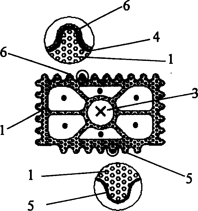
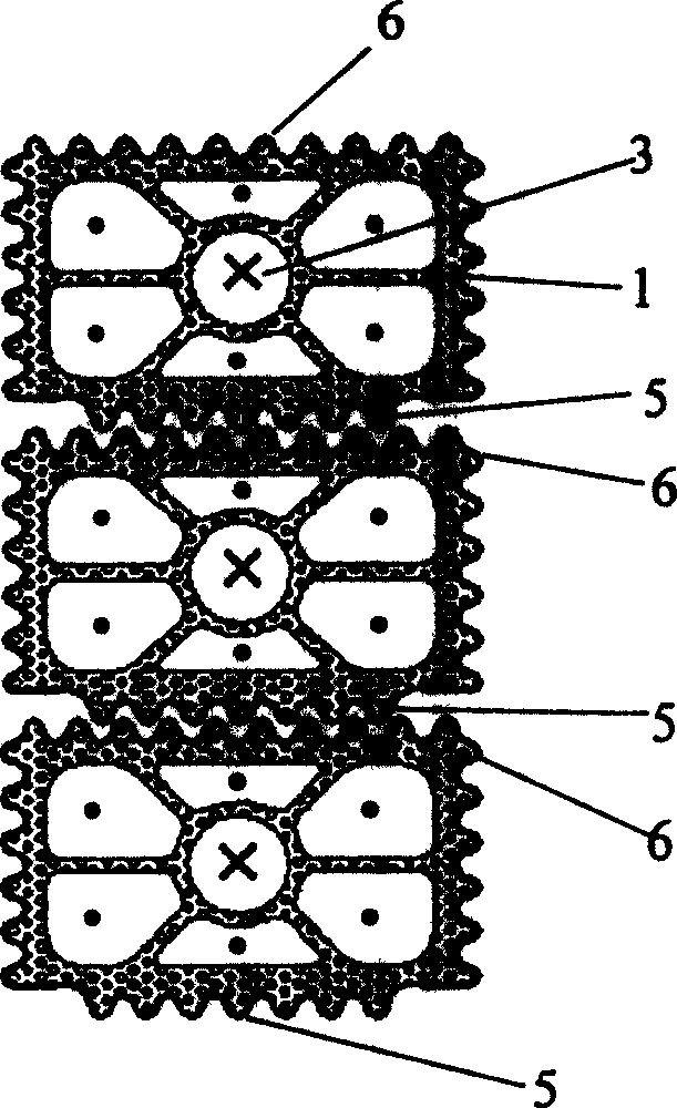
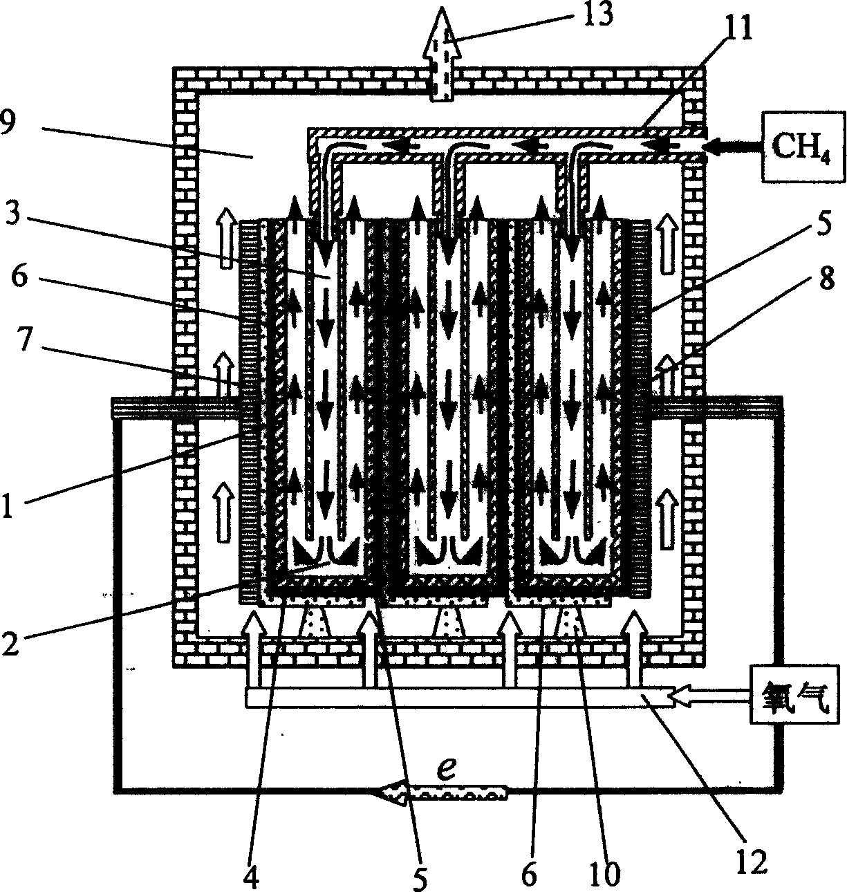
[0017] This embodiment is a tubular solid oxide fuel single cell with seven branch tubes in the inner layer tube 1 of the anode support. The anode material is Ni-YSZ cermet, the electrolyte is YSZ, and the cathode material is La 0.65 Sr 0.3 MnO 3-δ , the electrical connection material is La 0.8 Sr 0.2 CrO 3 . The production process is as follows:

[0018] Vacuum mud refining technology is adopted, cellulose (MC) is used as a bonding agent, and 60wt% NiO+YSZ ceramic mixed mud is mixed, and the upper part of the anode support inner layer tube 1 green body is formed by an extruder, and there are seven There are 6 branch pipes symmetrically distributed around the central branch pipe 3, the length of which is 600mm, the thickness of the partition wall between each branch pipe is ~0.8mm, the inner diameter of the central branch pipe 3 is 4mm, and the outer wall is composed of convex semicircular edges and concave The semicircular grooves are connected alternately and tangentia...

Embodiment 2

[0045] This embodiment is a tubular solid oxide fuel cell with three branch pipes in the inner layer tube 1 of the anode support. The grooves and ribs on the outer surface of the inner layer tube 1 have an equilateral triangle cross section, and the height of the triangle is 1 mm. The anode material is Fe-Al 2 o 3 Cermet, the electrolyte is YSZ, the cathode material is La 0.65 Sr 0.3 MnO 3-δ , the electrical connection material is La 0.8 Sr 0.2 CrO 3 ; The nominal section of the anode support inner layer tube 1 is oblate, and the inner diameter of the central branch tube 3 is 5 mm; the effective length of the battery reaction surface is 50 cm. The specific manufacturing process is the same as in Example 1 (so it is omitted). After the single cell is prepared, use 3mol / l Ni (NO 3 ) 2 aqueous solution, Ni(NO 3 ) 2 Immerse the inner wall of each branch of the inner tube 1. Before the operation of the battery stack, Ni(NO 3 ) 2 Decompose to obtain NiO, then pass fuel g...


PUM

PropertyMeasurementUnit
Thicknessaaaaaaaaaa
Lengthaaaaaaaaaa

Abstract

The present invention provides a tubular solid oxide fuel cell supported with anode,characterized by, multihole anode is used as strut body, layer tube in the strut body is divided into a plurality of branch pipes connected each other at bottom, the upper end of center branch pipe is connected with fuel tube, the cross-sectional shape for the outer wall of the inner layer tube is triangle or arched portrait grooves adjoining each other, in which, part of the outer surface for the abutting grooves is consecutive densify ionogen layer, and the other is consecutive densify electric interlock material layer, the consecutive densify ionogen layer and consecutive densify electric interlock material layer are interconnected so that the outer surface is completely covered, and thus forms airproof interlayer, the outside of the densify ionogen layer is multihole catodic layer, the convexconcave grooves increase effective response area, and improve power density of the body. The center branch pipe is used as fuel gas input pipe as well as fuel reforming reactor, so that separate reformer is omitted, and utilization efficiency of space in the strut body pipe is improved.

Description

Technical field: [0001] The invention belongs to the technical field of fuel cells, in particular to tubular solid oxide fuel cells. Background technique: [0002] The existing cathode-supported tubular solid oxide fuel cell technology was first developed by Westinghouse in the United States, using strontium-doped lanthanum manganate (abbreviated as SLMO) cathode material, yttrium-stabilized zirconia (YSZ) electrolyte, Ni-YSZ A cermet is used as the anode material, and a dense electrolyte layer ~40 μm thick is prepared by electrochemical vapor deposition (EVD). The Netherlands "International Solid State Ionics" magazine (Solid State Ionics, 135, 2000, 305-313) reported a flat tube solid oxide fuel cell developed by Siemens-Westinghouse, the main improvement of which is to make the cathode support body into a tube structure with supporting ribs. On the one hand, the supporting ribs play the role of increasing the cross-section of the current flow, reducing the internal resi...

Claims


Application Information

Patent Timeline
IPC IPC(8): H01M8/1226
CPCY02E60/521Y02E60/50
Inventor 孟广耀高建峰刘杏芹
Owner UNIV OF SCI & TECH OF CHINA
Why Eureka
Try Eureka