Sun light collected light-conduction tube transmission illumination device

A lighting device and light pipe technology, applied in the field of solar energy applications, can solve the problems of optical fiber transmission wavelength limitation, limited family economic affordability, long-distance optical fiber, low-loss transmission performance, low-cost manufacturing technology and high technical requirements, achieving low cost, The effect of simple processing technology

Inactive Publication Date: 2004-01-07
NANJING CHUNHUI SCI & TECH IND
View PDF3 Cites 10 Cited by
  • Summary
  • Abstract
  • Description
  • Claims
  • Application Information

AI Technical Summary

Problems solved by technology

[0005] Although the applicant of the present invention has made the performance and price ratio of the self-developed automatic tracking solar lighting device at the international leading level through successful research on multiple technologies such as light concentrating, tracking, and light transmission, but due to ...

Method used


Image

  • Sun light collected light-conduction tube transmission illumination device
  • Sun light collected light-conduction tube transmission illumination device
  • Sun light collected light-conduction tube transmission illumination device

Examples


Embodiment 1

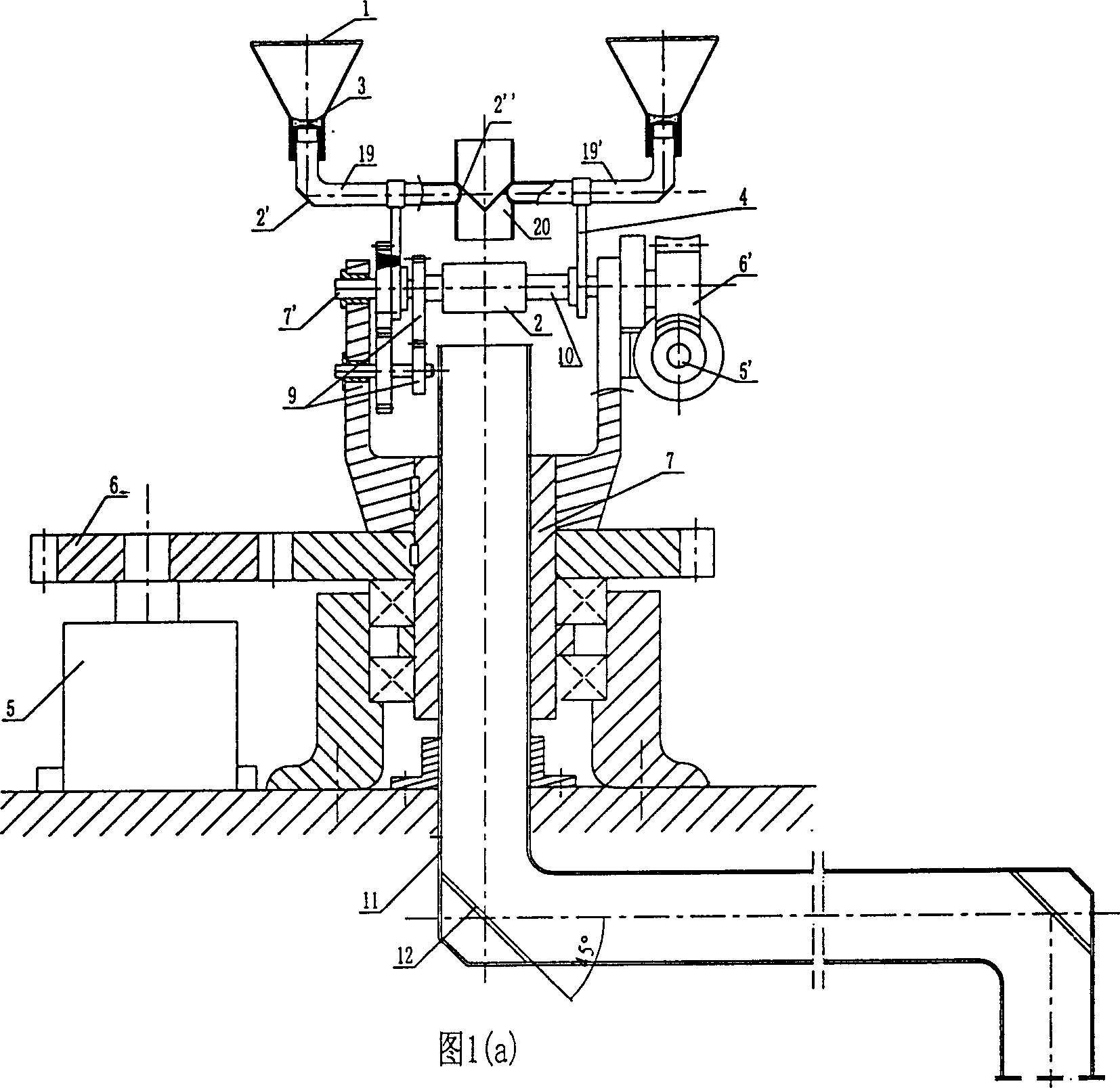
[0016] The basic structure of the light pipe transmission lighting device for collecting sunlight in this embodiment is shown in Figure 1(a), which mainly includes three parts: a lighting system, a light pipe transmission system, and a tracking system.

[0017] The lighting system is composed of Fresnel lens 1, concave collimating mirror 3, "L" shaped front light guide 19 and collective light guide 20, plane mirrors 2, 2', 2", and bracket 4. Fresnel The ear lens 1 and the concave collimating mirror 3 are installed at the entrance of the "L"-shaped front light guide tube 19 with a tapered frame structure, and each plane reflector is installed at each position to ensure that the incident light can be transmitted along the axis of the light guide tube. The turning point or transition of the light guide device. Specifically, the plane reflectors 2' and 2" are respectively installed at the turning point of the "L"-shaped front light guide tube 19 and the refraction point of the coll...

Embodiment 2

[0024] The basic structure of the light pipe transmission illuminating device that this embodiment gathers sunlight is identical with embodiment one, difference has two points: (1) the collimator mirror 3 of lighting system is a convex lens, keeps coaxial with Fresnel lens 1, The structure of the daylighting system is elongated like this; (2) all light pipes adopt square stainless steel tubes with inner wall mirrors, and the manufacturing cost is relatively low.

Embodiment 3

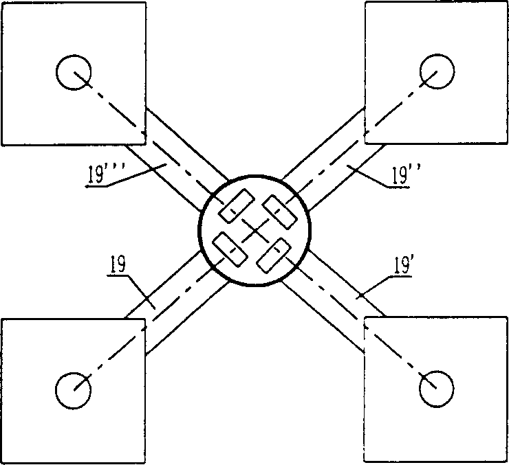
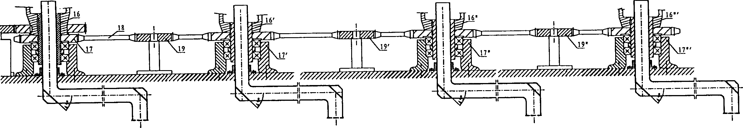
[0026] The light pipe transmission lighting device for collecting sunlight in this embodiment also includes two or more sets of lighting systems that are the same as those in Embodiment 1. The difference lies in that the hollow spindle mechanisms of the mechanical transmission devices of each lighting system are linked with each other. Specifically, the hollow main shafts of each daylighting system are respectively supported in their respective boxes, and are connected with each other through a chain 18 and a sprocket transmission linkage. One of the hollow main shafts is connected with the main shaft of the reversible motor through a reduction mechanism. For its structure, see figure 2 (Four sets of combinations are shown in the figure, the lighting system and the original mechanical transmission part are omitted, please refer to Figure 1).

[0027] Compared with Embodiment 1, due to the use of a linkage mechanism, only one set of driving device is needed to adjust the east-we...


PUM


Abstract

The device is composed of the lighting system, mechanical drive unit and the light pipe transmission system. The lighting system includes the lighting pipe composed of at least two 'L' shaped prepositive light pipes and the collecting light pipe located between the said 'L' shaped pipes. The lighting system through a bracket is connected to the assisting axis in the assisting axis mechanism. The principal axis in the principal axis mechanism is in hollowness type. Thus, the light pipe transmission system is installed inside the principal axis. The exit of the collecting light pipe is faced tothe entrance of the light pipe transmission system. The invented device can transfer visible light, infrared ray and ultraviolet radiation so as to use full spectrum of sunlight. The light pipe possesses effect of ideal total reflection. Thus light beam can be transmitted in long distance. The invention has the advantages of easy of manufacture and low cost.

Description

technical field [0001] The invention relates to a solar lighting lighting device, in particular to a lighting lighting device which relies on a light transmission device to transmit sunlight, and belongs to the technical field of solar energy applications. Background technique [0002] Lighting is one of the most energy-consuming needs of humans. According to statistics, lighting energy consumption in developed countries accounts for more than 9% of total energy consumption, and lighting energy consumption in developed areas of my country accounts for 6% to 9% of total energy consumption. Taking the United States as an example, the cost of lighting is as high as more than 100 million U.S. dollars every day, accounting for about 1 / 4 of the total power generation, but only 25% of the electricity used for lighting is actually used for lighting, and the rest is turned into heat. [0003] As we all know, sunlight is the most typical and most powerful natural light source, and it...

Claims


Application Information

Patent Timeline
IPC IPC(8): F21S11/00F21V8/00
CPCY02E10/47
Inventor 张耀明张文进徐明泉张振远孙利国陈强刘晓晖
Owner NANJING CHUNHUI SCI & TECH IND
Why Eureka
Try Eureka