Fuel cell system
A fuel cell system and fuel cell technology, used in fuel cells, fuel cell additives, circuits, etc., can solve problems such as breaking the pressure balance, blocking the fuel supply path, and stopping the operation of the fuel cell system.
- Summary
- Abstract
- Description
- Claims
- Application Information
AI Technical Summary
Problems solved by technology
Method used
Image
Examples
Embodiment 1
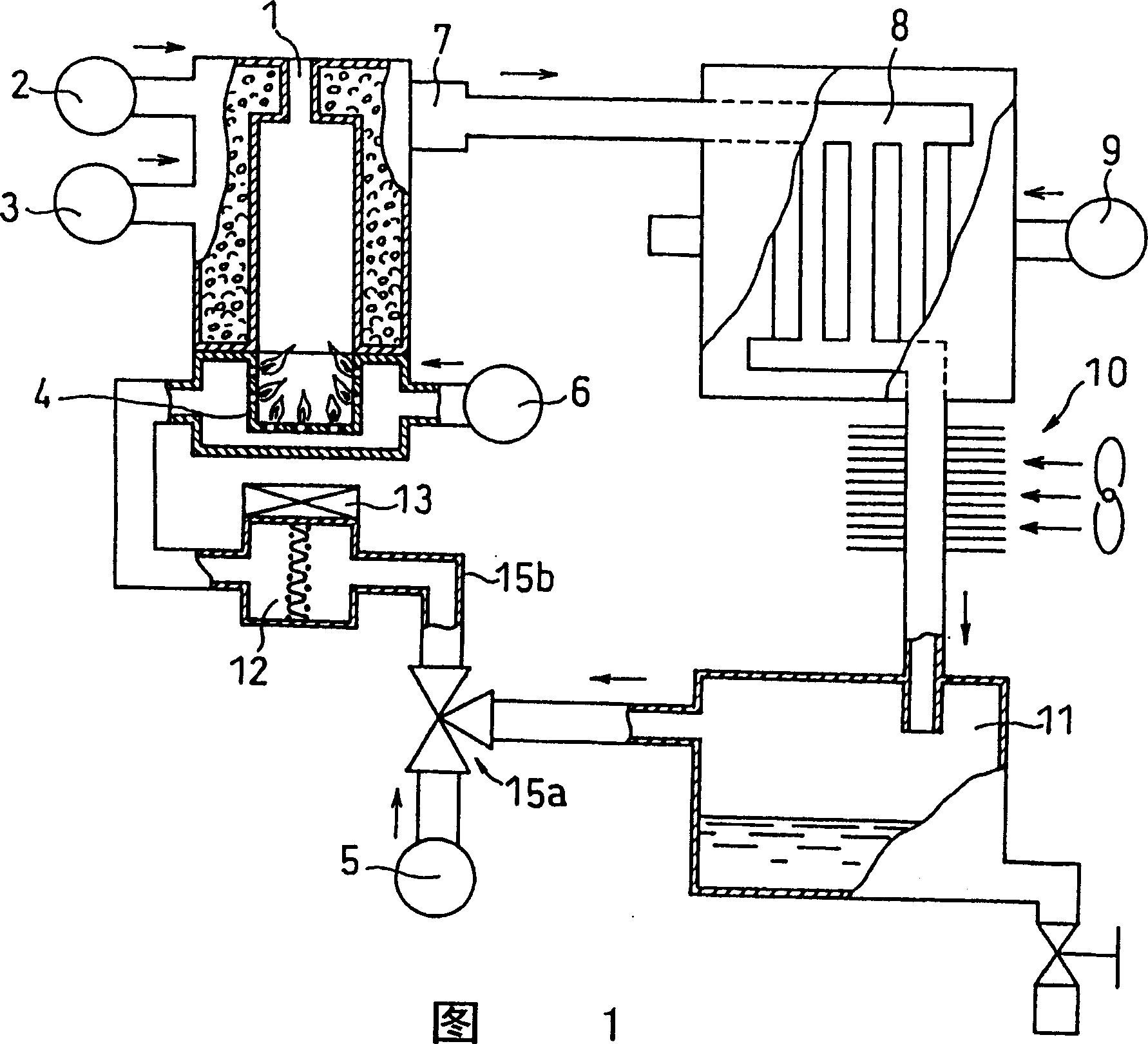
[0027] FIG. 1 is a schematic diagram showing the configuration of a fuel cell system according to Embodiment 1 of the present invention. The fuel cell system of Example 1 has a reforming unit 1 in which a reforming catalyst is incorporated, a raw material supply unit 2 for supplying raw materials to the reforming unit 1, a water supply unit 3 for supplying water to the reforming unit 1, and a combustion furnace 4 for heating the reforming catalyst. . In the reforming section 1, the raw material (gas) and water react to produce hydrogen. In addition, a fuel supply unit 5 for supplying fuel to the combustion furnace 4 and an air supply unit 6 for supplying air to the combustion furnace 4 are provided.
[0028] Here, as the raw materials and fuels respectively supplied from the raw material supply unit 2 and the fuel supply unit 5, gaseous hydrocarbon fuels such as natural gas (city gas) and LPG, liquid hydrocarbon fuels such as gasoline and kerosene, and alcohols such as methan...
Embodiment 2
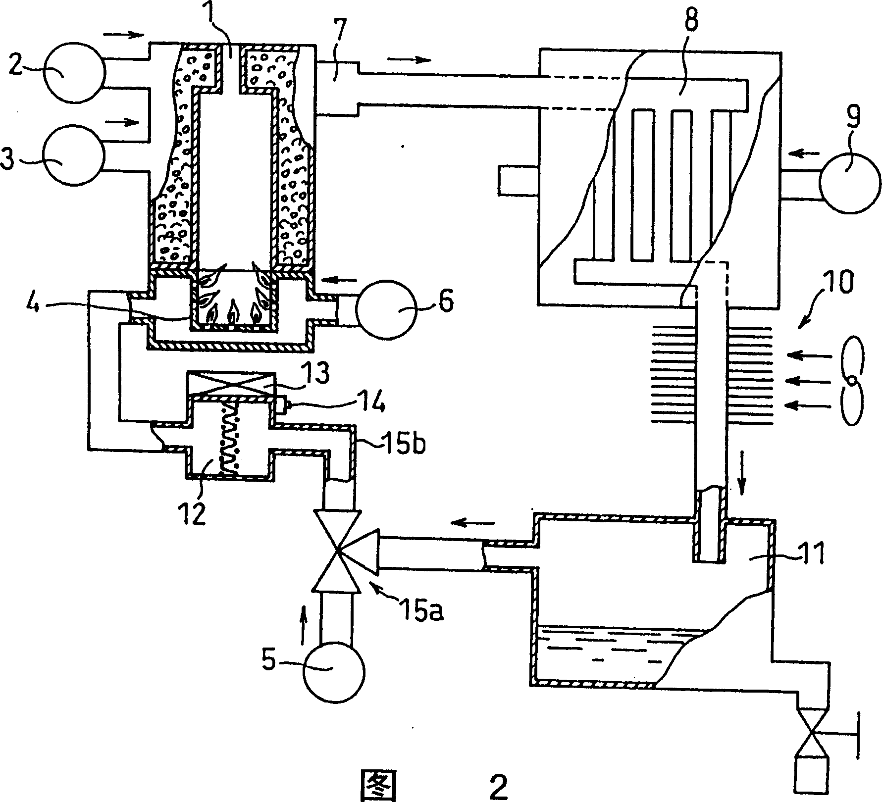
[0040] Fig. 2 is a schematic structural view of the fuel cell system in Embodiment 2 of the present invention. Embodiment 2 differs from Embodiment 1 in that, as shown in FIG. 2 , a first temperature detector 14 is arranged near the fireproof part 12 , and the operation of the heater 13 is controlled according to the signal of the temperature detector 14 . In addition, the control part which controls the operation of the heater 13 based on the signal of the temperature detector 14 is not shown in a figure.
[0041] For example, a thermistor can be used as the first temperature detector 14 . Other than thermistors, for example, thermocouples and platinum resistors can be used.
[0042] The first temperature detector 14 may be arranged at a position in contact with the fireproof part 12, or may be arranged at a position where the temperature of the fireproof part 12 can be detected indirectly. Furthermore, the second temperature detector may be disposed at a position where hea...
Embodiment 3
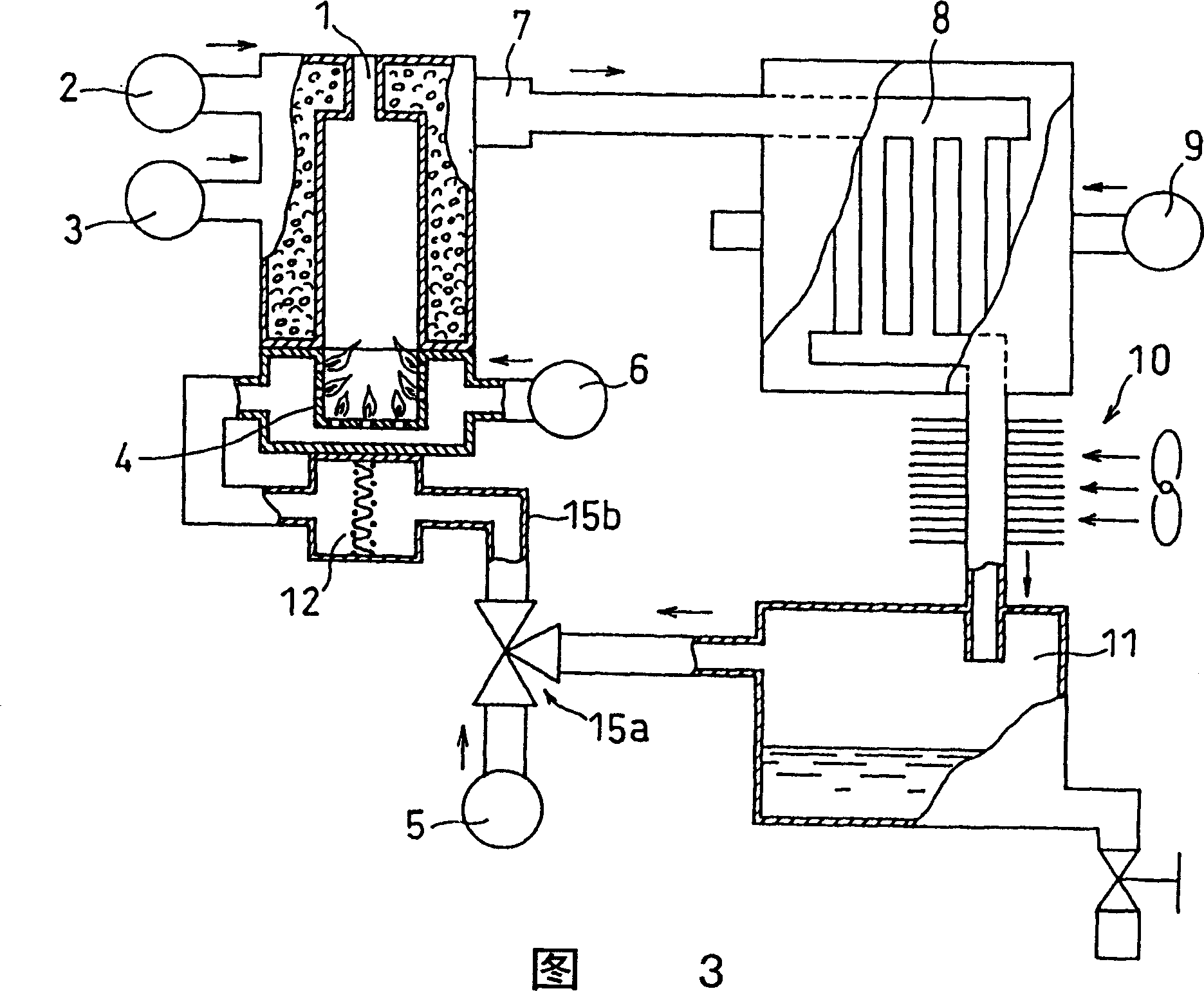
[0048] Fig. 3 is a schematic diagram showing the configuration of a fuel cell system according to Embodiment 3 of the present invention. Embodiment 3 differs from Embodiment 1 in that, as shown in FIG. 3 , the fire prevention part 12 is arranged adjacent to the high-temperature combustion furnace 4 or the conversion part 1 to absorb the heat from these parts. The fire prevention part 12 can have a temperature equal to or higher than the dew point of the exhaust gas because heat can be obtained from these parts.
[0049] In this embodiment, since the combustion furnace 4 and the fire prevention part 12 are integrally formed, the heat from the combustion furnace 4 is easily transferred to the fire prevention part 12 by heat conduction. The temperature of the internal combustion part of the combustion furnace 4 is about 1000°C, and the reaction temperature of the reforming catalyst inside the reforming part 1 is about 700°C. Therefore, it is possible to use a method of transferr...
PUM
 Abstract
Description
Claims
Application Information
 - R&D
- Intellectual Property
- Life Sciences
- Materials
- Tech Scout
- Unparalleled Data Quality
- Higher Quality Content
- 60% Fewer Hallucinations
Browse by: Latest US Patents, China's latest patents, Technical Efficacy Thesaurus, Application Domain, Technology Topic, Popular Technical Reports.
© 2025 PatSnap. All rights reserved.Legal|Privacy policy|Modern Slavery Act Transparency Statement|Sitemap|About US| Contact US: help@patsnap.com


