
Photocatalyst film having light activity visible basal body and method for preparing the same

A photocatalyst and visible light technology, applied in catalyst activation/preparation, chemical instruments and methods, physical/chemical process catalysts, etc., can solve the problems of no visible light activity, no red shift of absorbed light, and insignificant red shift of absorbed light, etc. Achieve good self-cleaning and anti-fog effects and high visible light activity

Inactive Publication Date: 2004-01-14
GUANGZHOU INST OF ENERGY CONVERSION - CHINESE ACAD OF SCI
View PDF10 Cites 22 Cited by
  • Summary
  • Abstract
  • Description
  • Claims
  • Application Information

AI Technical Summary

Problems solved by technology

[0004] The purpose of the present invention is to overcome the shortcomings of the existing photocatalyst film that the absorption light red shift is not significant, the main absorption light is not red shifted, the degree of red shift in the visible light region of 388-500 is small, and there is no visible light activity, and to provide a Photocatalyst film with absorption red shift and high visible light activity, better self-cleaning and anti-fog effects and preparation method thereof

Method used


Image

  • Photocatalyst film having light activity visible basal body and method for preparing the same
  • Photocatalyst film having light activity visible basal body and method for preparing the same
  • Photocatalyst film having light activity visible basal body and method for preparing the same

Examples


Embodiment 1

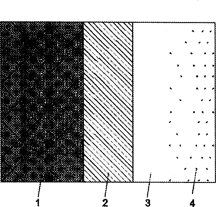
[0025] The visible-light-active photocatalyst film structure on the substrate is as follows: figure 1 shown. In the figure, SiO is deposited on the base glass (1) 2 Thin film layer (2) and semiconductor photocatalyst layer TiO 2 (3), TiO 2 Tungsten oxide (4) was deposited on the surface to realize the doping modification of the photocatalyst by metal ions. (a) SiO on substrate 2 Film preparation

[0026] Preparation of silica sol: take 100ml of absolute ethanol, 104ml of tetraethyl orthosilicate, and 160ml of absolute ethanol in a 500ml Erlenmeyer flask at 900rpm and stir for 1hr, then slowly drop 26ml of HCl (2M) into the above Erlenmeyer flask while stirring evenly After dripping, continue to stir for 1 hr, and stand in the dark for 24 hr to obtain silica sol.

[0027] Ordinary glass pieces (200mm×34mm×2mm) were soaked in acid solution, potassium dichromate lotion solution and distilled water, washed and dried. Dip the pulled glass piece once in silica sol (2mm s -1 ...

Embodiment 2

[0033] WO is sputtered with embodiment 1 step (c) 3 TiO 2 film at N 2 2°C·min under protection -1 Program the temperature to 500°C and keep the temperature constant for 5 hours. (The sample is recorded as H-5hr for later testing).

Embodiment 3

[0034] Example 3 (a) SiO on the substrate 2 Film preparation: same as Example 1. (b) SiO 2 TiO on film 2 Film preparation:

[0035]Preparation of titanium sol: Take 110ml of absolute ethanol, 68ml of tetrabutyl titanate, 16.5ml of diethanolamine, and 100ml of absolute ethanol in a 500ml Erlenmeyer flask at 900rpm and stir for 1hr. 3.6mlH 2 O was slowly added dropwise to the above Erlenmeyer flask, and after the drop, continued to stir for 0.5 hr, and left to stand in the dark for 24 hr to obtain titanium sol. Where molar ratio Ti(OBu) 4 : C 2 h 5 OH:H 2 O:NH(C 2 h 4 Oh) 2 =1:26.5:1:1.

[0036] Will have SiO on the surface 2 The glass sheet of the film was dipped and pulled once in titanium sol (2mm s -1 ), bake in an electric drying oven at 100°C for 10 minutes, and repeat the process from pulling to drying 5 times. (c) WO on substrate film 3 preparation of

[0037] Using the current adjustable magnetron sputtering apparatus, the output power is 1350W (450V×3....


PUM


Abstract

A photocatalyst film with visual light activity has SiO2 layer and photocatalyst layer, and is prepared through preparing SiO2 film on a substrate by sol-gel method, preparing TiO2 film on SiO2 film by sol-gel method, sputtering metal or metal oxide by magnetically controlled sputter method, and heat treatment in inertial gas at 300-600 deg.C for 0.5-10 hr for diffusing the metal or metal oxide into TiO2 film. Its advantages are high visual light activity, and good self-cleaning and antifog effect.

Description

technical field [0001] The invention relates to a photocatalyst thin film with visible light activity on a substrate and a preparation method thereof. Background technique [0002] The photocatalyst film has self-cleaning and anti-fog effects. Car windshields, window glass, building window glass, glasses lenses, glass surfaces of instruments and other substrates will greatly reduce the transparency of transparent substrates due to condensation of water vapor into fog, splashing of rainwater, adhesion of organic pollutants, etc. It becomes dirty, difficult to clean, and takes time and money. Cleaning glass in high-rise buildings is also dangerous. Also, household utensils, such as pottery, etc., especially toilet pottery can easily lead to the reproduction and growth of bacteria, affecting people's health. A large number of documents have reported that photocatalysts such as titanium dioxide form a thin film on the surface of the substrate, which has the functions of anti-f...

Claims


Application Information

Patent Timeline
Patent Type & Authority Applications(China)
IPC IPC(8): B01J21/06B01J23/24B01J23/745B01J35/00B01J37/02
Inventor 张琦王良焱李新军何明兴梁园园
Owner GUANGZHOU INST OF ENERGY CONVERSION - CHINESE ACAD OF SCI
Learn More