Transmission apparatus using a plastic fiber

A technology of plastic optical fiber and transmission device, which is applied to the device for controlling the output parameters of the laser, the coupling of the cladding fiber, the optical waveguide, etc. , the effect of distance extension, stable transmission characteristics

Inactive Publication Date: 2004-01-14
FUJIFILM CORP
View PDF0 Cites 2 Cited by
  • Summary
  • Abstract
  • Description
  • Claims
  • Application Information

AI Technical Summary

Problems solved by technology

[0012] In this case, the above-mentioned problem can be solved by using Peltier elements used in mainline optical communication and keeping the temperature constant by heating and cooling. However, at this time, the cost of the transmission device increases due to the expensive Peltier elements.

Method used


Image

  • Transmission apparatus using a plastic fiber
  • Transmission apparatus using a plastic fiber
  • Transmission apparatus using a plastic fiber

Examples


Embodiment Construction

[0036] Hereinafter, embodiments of the present invention will be described with reference to the drawings.

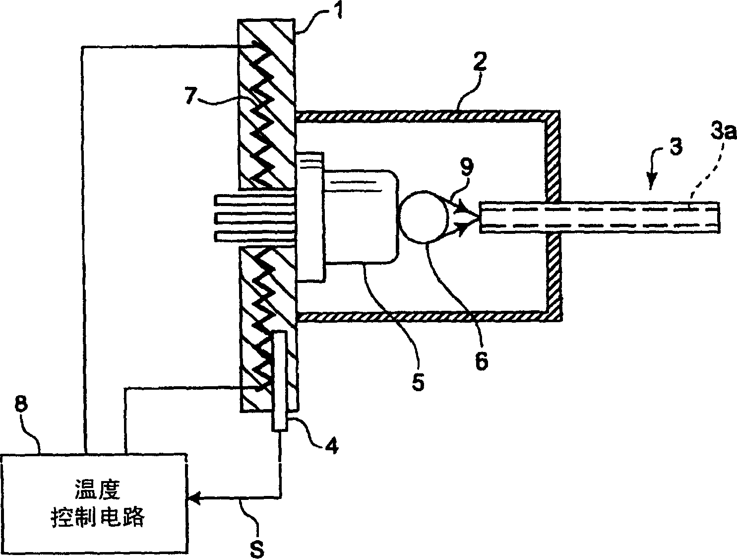
[0037] figure 1 A partly cutaway side view showing a transmission device using a plastic optical fiber according to the first embodiment of the present invention. The part shown here is a part constituting the optical signal transmission module part, and includes a substrate 1, a can-shaped housing 2 mounted on the substrate 1, and a plastic optical fiber whose one end is inserted into the housing 2 as shown in the figure. 3. The thermistor 4 disposed in the hole penetrated into the substrate 1, the column part is installed on the above-mentioned substrate 1 and the end surface emitting semiconductor laser 5 housed in the housing 2 is also housed in the housing 2 The ball lens in 6. Furthermore, an electric heater 7 is built in the substrate 1, and a temperature control circuit 8 is provided to drive the electric heater 7 based on an output signal from the thermistor...


PUM


Abstract

In the transmission apparatus comprising a PMMA plastic fiber 3 and a semiconductor light emitting element 5 to emit the light 9 transmitted through the plastic fiber 3, the element which can emit the light 9 having the wavelength within the range of 630 to 680 nm is used as the semiconductor light emitting element 5. Moreover, there is provided a temperature adjusting mechanism comprising a heating means 7 for heating the semiconductor light emitting element 5, a temperature detecting means for detecting the temperature of the semiconductor light emitting element 5, and a control circuit 8 for setting the temperature of the semiconductor light emitting element 5 to a predetermined target value which is lower than the maximum temperature assumed under the environment for locating thereof by controlling the drive of the heating means 7 based on a temperature detecting signal S outputted from the temperature detecting means 4.

Description

technical field [0001] The present invention relates to a transmission device using a plastic optical fiber used in an optical communication system or the like. Background technique [0002] Generally, a single-mode or multi-mode optical fiber mainly made of silica glass is used as a transmission path of light in optical communication. The diameter of these optical fibers is less than 200 μm, and high positioning accuracy in micron units is also required in positioning. For this reason, it is difficult to perform optical fiber laying work in a general environment such as a work site, and this is a major factor hindering further popularization. [0003] On the other hand, although large-diameter plastic optical fibers that are easier to install have also been developed, due to manufacturing problems, they are mainly mutation-type structures and cannot transmit high-speed signals over long distances. That is, when an optical pulse is input into an abrupt optical fiber, after...

Claims


Application Information

Patent Timeline
Patent Type & Authority Applications(China)
IPC IPC(8): B41J2/44B41J2/45B41J2/455B41J2/46G02B6/02G02B6/42H01L33/48H01S5/022H01S5/06H01S5/068
CPCG02B6/02H01S5/06804H01S5/0612B41J2/46G02B6/4201H01S5/02453H01S5/02284H01S5/0224G02B6/4246G02B6/4271H01S5/02251H01S5/0234G02B6/43
Inventor 早川利郎
Owner FUJIFILM CORP
Why Eureka
Try Eureka