Objective lens for optical pickup
A pickup and objective lens technology, which is applied in the field of objective lenses, can solve the problems of difficult metal model processing, easy wear, and increased production costs, and achieve the effects of suppressing the reduction of optical performance of the objective lens, low manufacturing cost, and simple processing
- Summary
- Abstract
- Description
- Claims
- Application Information
AI Technical Summary
Problems solved by technology
Method used
Image

Examples
no. 1 example
[0140] According to the first embodiment of the invention, C=-0.998, δ=0.1912, λ=660 nm, n=1.54044, λ′=668 nm and n′=1.54015. at this time
[0141] N=δ / (λ(n'-1) / ((n-1) / λ')-1)
[0142] =0.1912 / (660(1.54015-1) / ((1.54044-1)668)-1
[0143] =-15.36218 That is to say, when the optical path difference is Nλ, the wavefront aberration formed by the step S will introduce the required value when the temperature changes. However, if the optical path difference formed by the step S includes a fractional part, aberrations will be generated in the reference state (before temperature rise). Therefore, in the reference state, the optical path difference at the step S should be an integer. In this way, the actual height difference at the step S is the value after the decimal part is rounded off, for example, N=-15.
[0144] The step S should be formed so that the optical path of the light passing through the peripheral area of the step S is 15λ longer than the optical path of the light ...
no. 1 approach
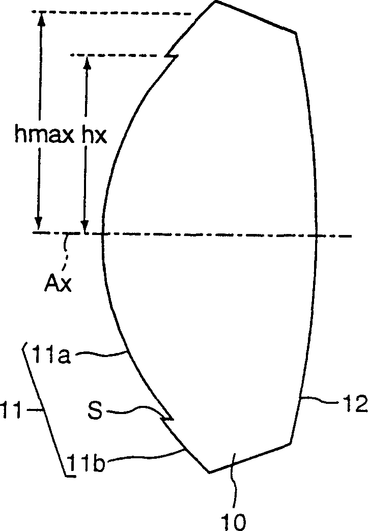
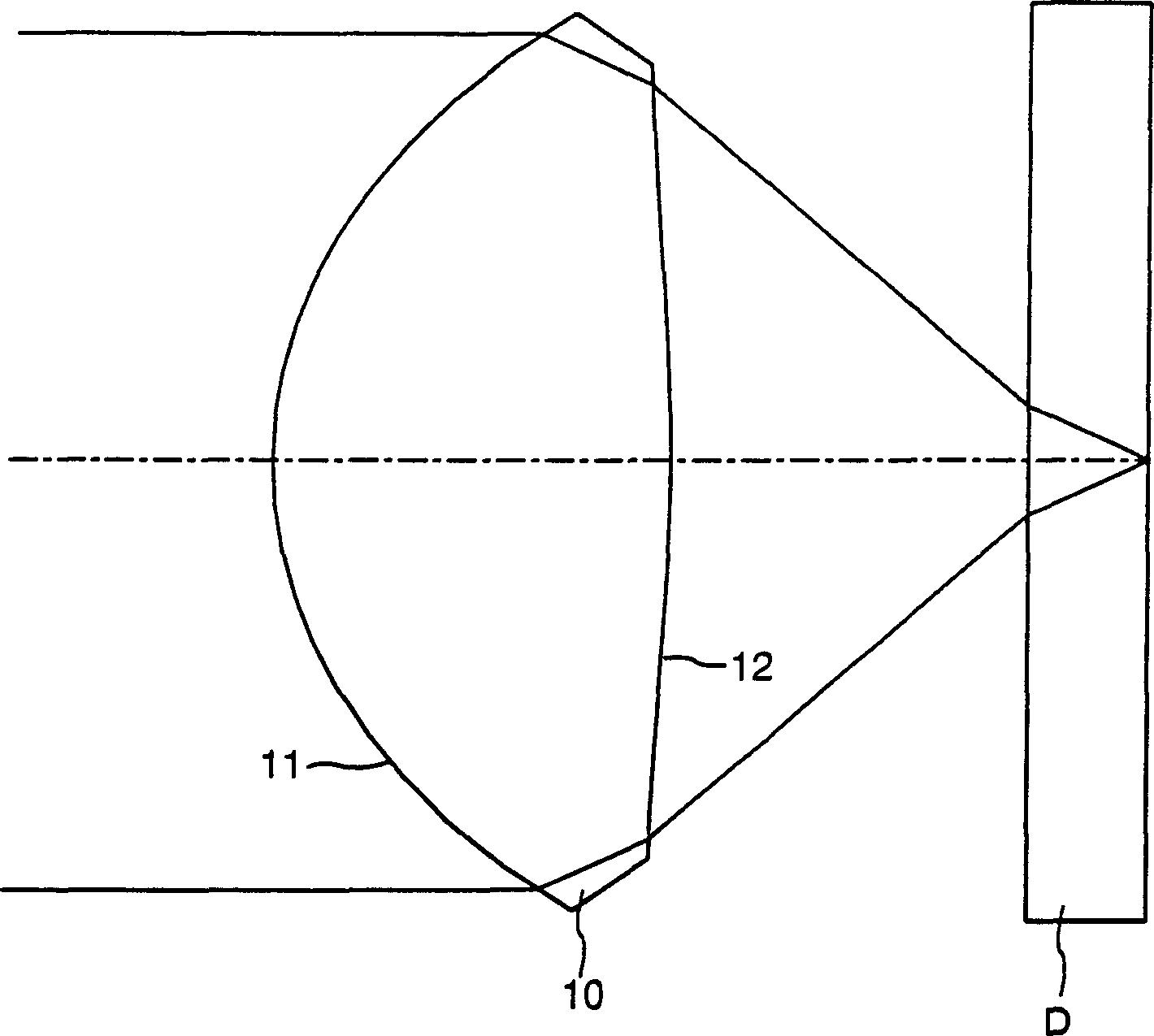
[0155] figure 2 It is a schematic diagram showing the objective lens 10 and the cover film D of the optical disc. Note that in the lens arranged in this embodiment, the step S adopts the same magnification ratio as other parts, so the height of the step S cannot be represented as a visible step in the diagram.
[0156] The structural parameters are shown in Table 1. In Table 1 and the tables of other embodiments, f represents the focal length, NA represents the numerical aperture, λ represents the design wavelength, r represents the radius of curvature of the lens surface (unit: mm), and d represents the distance between adjacent surfaces on the optical axis (unit: mm), and n is the refractive index at the design wavelength. , surface numbers #1 and #2 represent the first surface 11 and the second surface 12 of the objective lens 10, respectively, and surface numbers #3 and #4 represent the two coating surfaces D of the optical disc, respectively.
[0157] f=3.30m...
no. 2 approach
[0168] Figure 6 It is a schematic diagram of the objective lens 10 and the optical disc coating D, and the structural parameters are shown in Table 3.
[0169] f=3.00mm NA=0.60λ=660nm
the surface
r
d
n
1
1.9000
1.8000
1.54044
2
-7.3800
1.6230
-
3
∞
0.6000
1.57961
4
∞
-
-
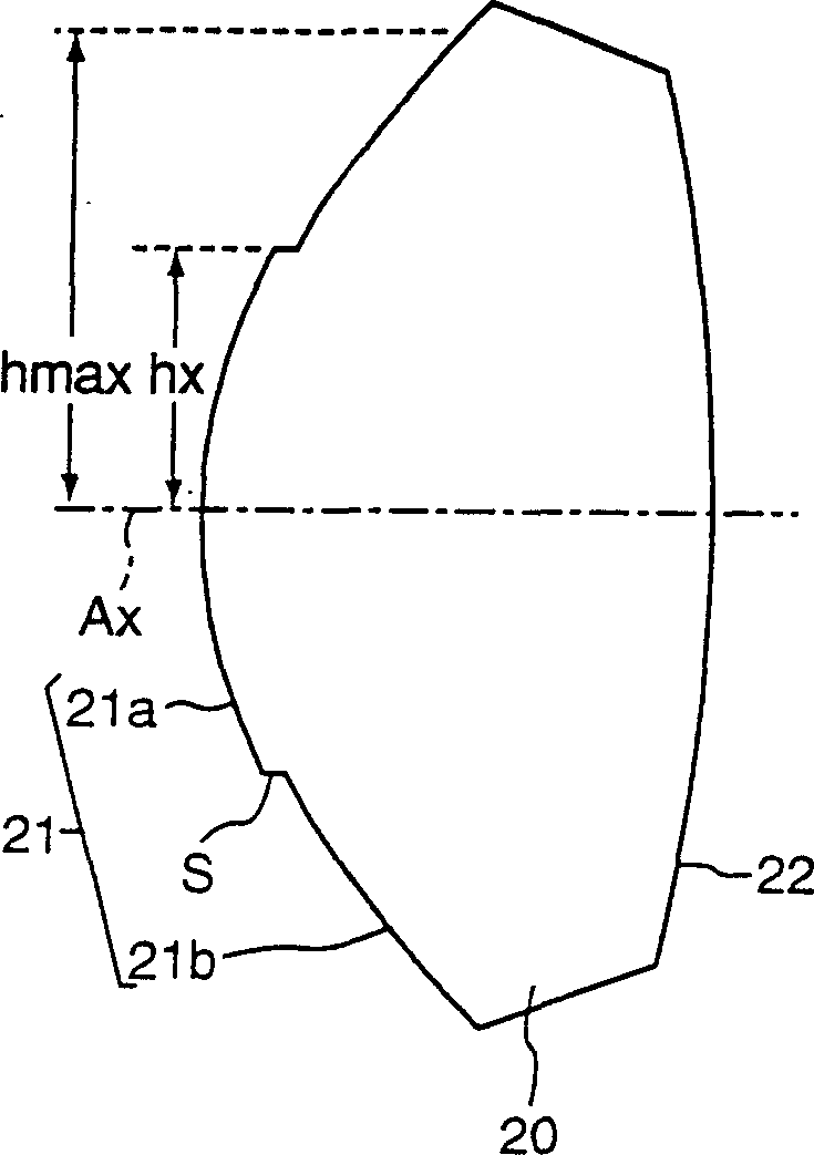
[0170] The first surface 11 is divided into a central region and a peripheral region by a boundary having a height hx with respect to the optical axis. The central area is lower than the peripheral area. These regions may be aspherical surfaces with different shapes but with rotational symmetry, and steps S are formed between the regions (ie, there is a height difference). The second surface 12 is also a rotationally symmetrical aspheric surface without steps.
[0171] Effective radius hmax, boundary height hx, paraxial ...
PUM
| Property | Measurement | Unit |
|---|---|---|
| thickness | aaaaa | aaaaa |
| thickness | aaaaa | aaaaa |
| thickness | aaaaa | aaaaa |
Abstract
Description
Claims
Application Information
 - R&D Engineer
- R&D Manager
- IP Professional
- Industry Leading Data Capabilities
- Powerful AI technology
- Patent DNA Extraction
Browse by: Latest US Patents, China's latest patents, Technical Efficacy Thesaurus, Application Domain, Technology Topic.
© 2024 PatSnap. All rights reserved.Legal|Privacy policy|Modern Slavery Act Transparency Statement|Sitemap