Analog control circuit for fan driving and controlling method thereof

A technology of analog control and differential amplifier circuit, applied in the direction of motor control, DC motor speed/torque control, control system, etc., can solve the problems of low efficiency, annoying, high cost, etc., and achieve simple equipment and heat resistance Good, the effect of improving efficiency

Inactive Publication Date: 2004-01-21
KOMATSU LTD
View PDF0 Cites 6 Cited by
  • Summary
  • Abstract
  • Description
  • Claims
  • Application Information

AI Technical Summary

Problems solved by technology

[0004] However, in the above-mentioned analog circuit, since the rotation speed of the electric motor or the hydraulic motor will change in steps once it reaches the set temperature, it will be changed at the change point ( Image 6 Ya point, Yb point shown) produces a loud sound, which is annoying
In addition, since the rotation speed of the electric motor or the hydraulic motor is changed stepwise, there will be a problem of low efficiency.
Compared with analog circuits, the cost of digital circuits such as digital regulators using microprocessors becomes higher
In addition, since the circuit becomes complicated, troubleshooting and maintenance become difficult

Method used


Image

  • Analog control circuit for fan driving and controlling method thereof
  • Analog control circuit for fan driving and controlling method thereof
  • Analog control circuit for fan driving and controlling method thereof

Examples


Embodiment Construction

[0027] specific implementation

[0028] Hereinafter, embodiments of the analog circuit for driving a fan according to the present invention will be described with reference to the drawings.

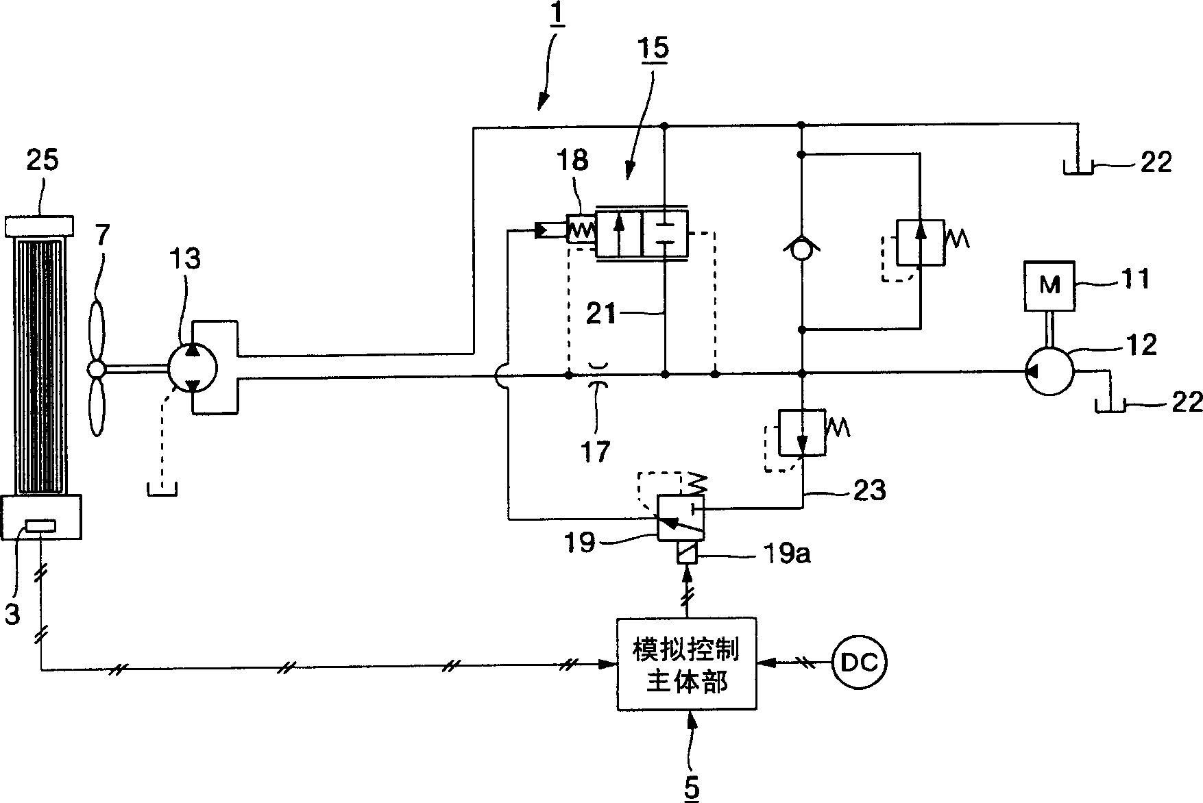
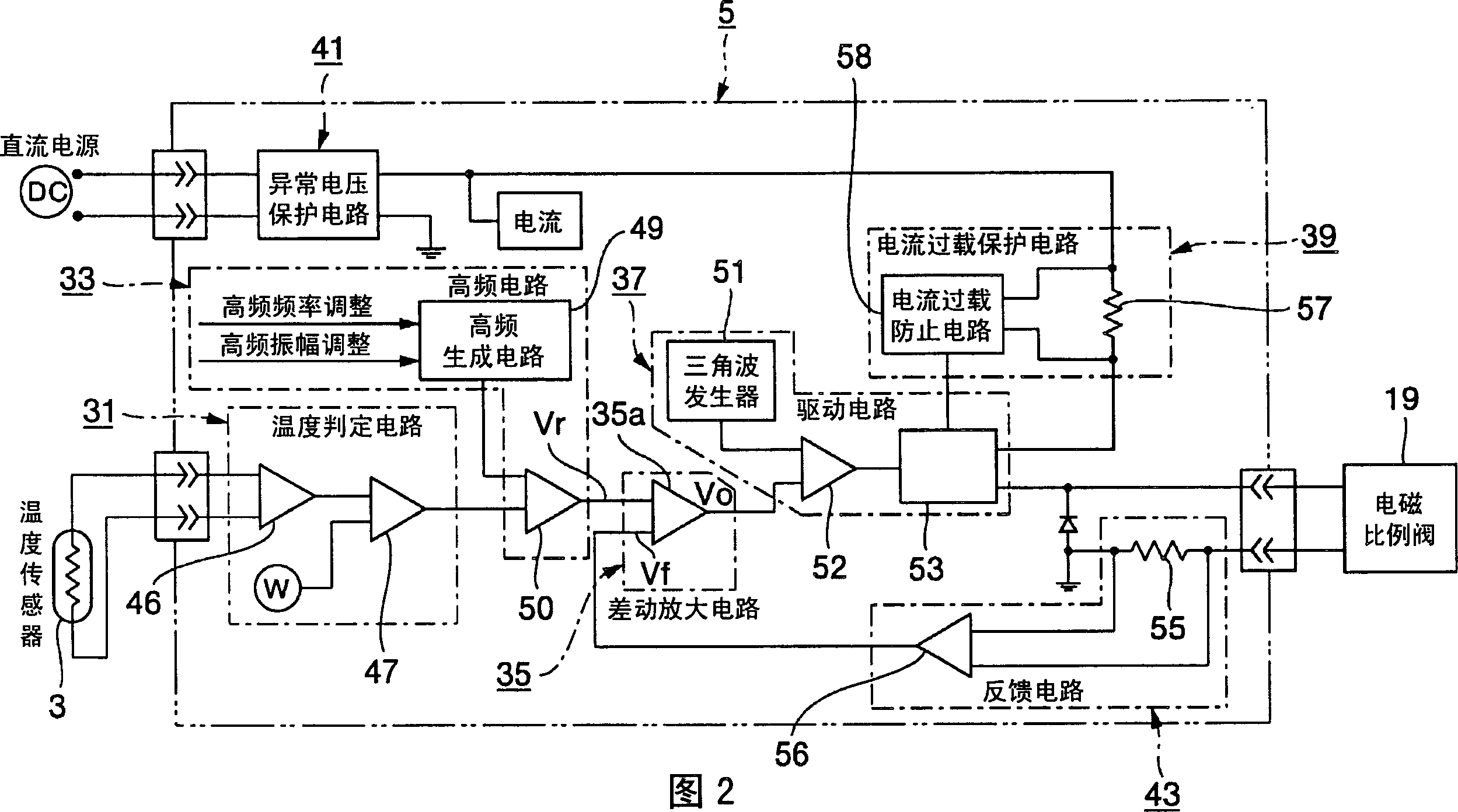
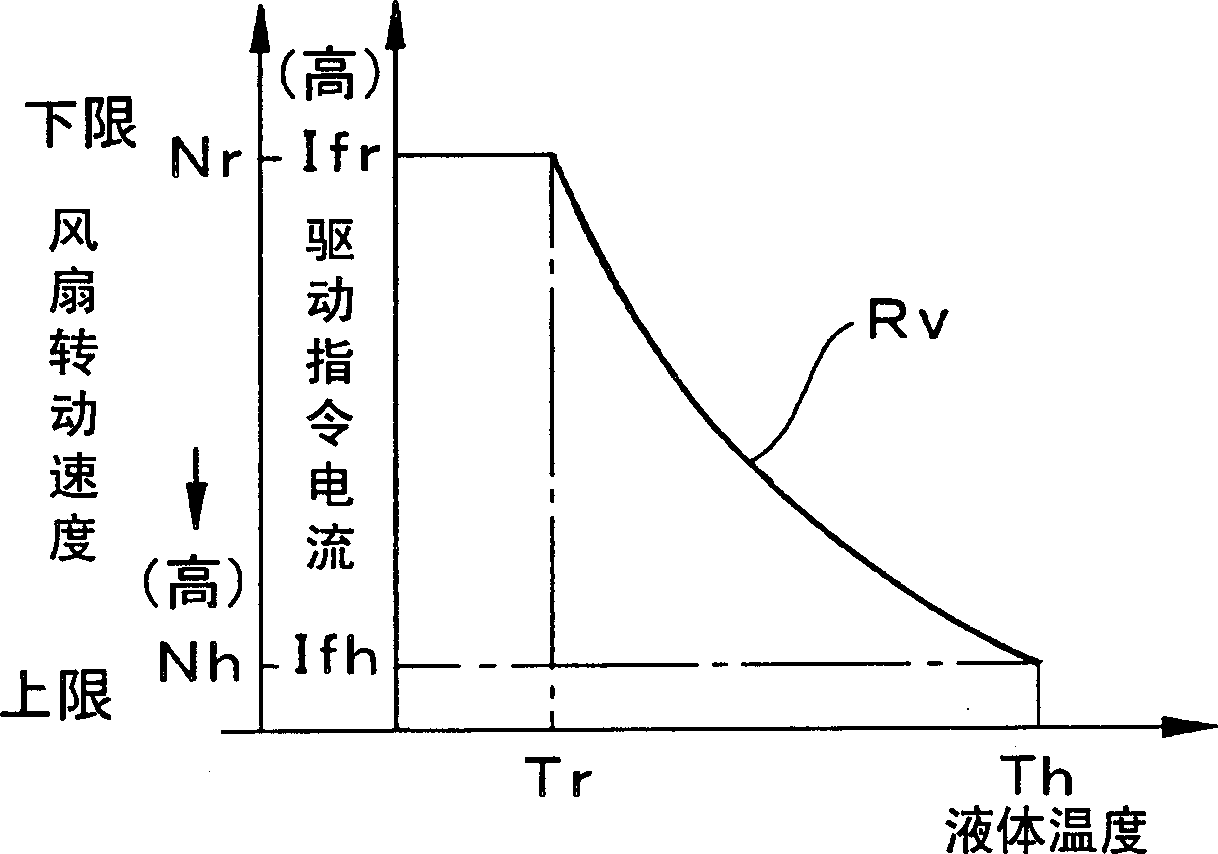
[0029] First, refer to Figure 1 to Figure 5 An example of an analog circuit for driving a fan will be described. figure 1 It is a circuit diagram of the analog control circuit for driving the fan, and Fig. 2 is a circuit diagram of the main part of the analog control for driving the fan, image 3 It is an explanatory diagram of the relationship between liquid temperature, fan rotation speed and drive command current, Figure 4 is an illustration of an example of correcting an input value to an output target value. Figure 5 It is an explanatory diagram of an example of comparing and switching between a triangle wave and a command current.

[0030] figure 1 It is a schematic diagram of an example of an analog control circuit 1 for driving a fan. The analog control circuit 1 for dri...


PUM


Abstract

This analog control circuit for driving the fan comprises a DC power source, a temperature sensor detecting a temperature of a liquid to be cooled by the fan, and outputting a temperature signal in proportion to the temperature, a temperature determining circuit receiving the temperature signal and outputting a first command current corresponding to the temperature, a differential amplification circuit for amplifying the first command current and outputting the same as a second command current, a drive circuit receiving the second command current and the DC current and outputting the drive command current to an electromagnetic proportional valve, and the electromagnetic proportional valve receiving the drive command current and controlling a rotating speed of the fan.

Description

technical field [0001] The invention relates to an analog control circuit for driving a fan and a control method for the analog circuit for driving the fan by continuously rotating the fan steplessly to cool liquid. Background technique [0002] Conventionally, in a vehicle driven by an engine, the cooling of the engine and the cooling of lubricating oil have been carried out by using a rotating fan to send cold air. The rotation of the fan includes a type that is driven by a belt from an engine and a type that is performed by an electric motor or a hydraulic motor independent of the engine. In the type in which the fan is driven by the electric motor or hydraulic motor, the temperature of the engine cooling water or lubricating oil is measured, and the electric motor or hydraulic motor is switched on or off according to the temperature, or the rotational speed is changed stepwise to control the cooling water or lubricating oil of the engine The temperature of the oil is in...

Claims


Application Information

Patent Timeline
Patent Type & Authority Applications(China)
IPC IPC(8): F01P7/04F15B9/09F15B11/02H02P7/00H02P29/00H02P29/60
Inventor 赤松隆志山元裕一丸田和弘
Owner KOMATSU LTD
Why Eureka
Try Eureka