Speed controller for synchronous machine

A speed control device, synchronous motor technology, applied in motor generator control, AC motor control, single motor speed/torque control, etc. current, etc.

Active Publication Date: 2004-01-21
HITACHI JOHNSON CONTROLS AIR CONDITIONING INC
View PDF2 Cites 40 Cited by
  • Summary
  • Abstract
  • Description
  • Claims
  • Application Information

AI Technical Summary

Problems solved by technology

That is, in the current reproduction method, since the motor current is reproduced based on the DC current of the inverter and the gate pulse signal of the inverter, when the command voltage is low and the pulse width of the gate pulse is extremely short at the time of starting, etc., It is difficult to capture the current component of the motor
In particular, when the speed of the motor is increased, the higher the average switching frequency (carrier frequency) of the inverter is set, the shorter the pulse width of the gate pulse is, and the more difficult it is to reproduce the current
As a countermeasure against this, the carrier frequency of the inverter

Method used


Image

  • Speed controller for synchronous machine
  • Speed controller for synchronous machine
  • Speed controller for synchronous machine

Examples


Embodiment Construction

[0042] Hereinafter, an embodiment of the present invention will be described with reference to the drawings.

[0043] Embodiment 1

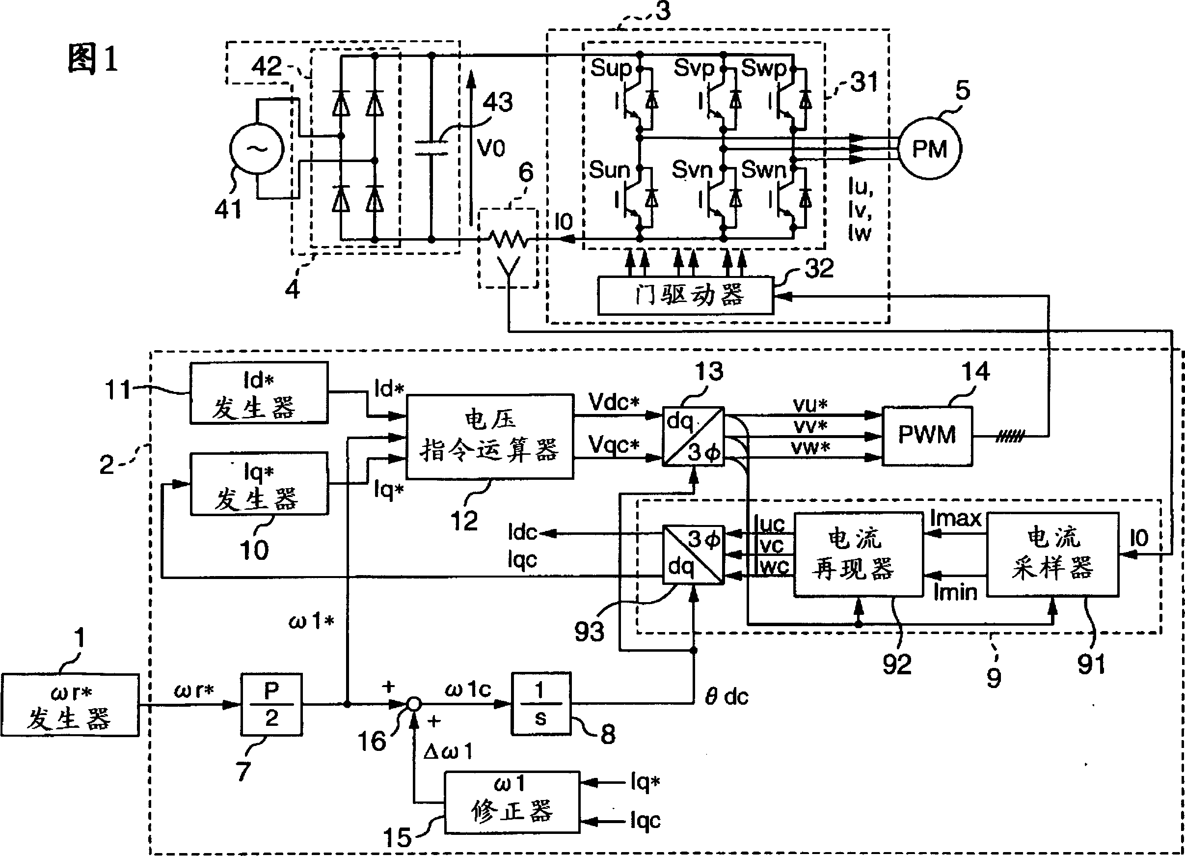
[0044] Fig. 1 is a block diagram showing a system configuration of Embodiment 1 of a speed control device for a synchronous motor according to the present invention. In Fig. 1, the speed control device of the synchronous motor is constituted as having a generator for providing the rotational speed command ωr to the synchronous motor 5 * The revolution command ωr * The number of revolutions instruction generator 1 of computing; The AC applied voltage of synchronous motor 5 is calculated, according to this calculation result, generates the pulse width modulation signal (PWM signal) as pulse width control signal, is applied to the controller 2 on the inverter 3; Inverter 3 driven by this PWM signal; DC power supply 4 to supply power to inverter 3; current detector (inverter current The detector) 6 is connected to the AC output side of the inverte...


PUM


Abstract

In order to rotate a motor stably at a high speed without using a magnetic pole position sensor and a current sensor, an electrical angle frequency command omega1* is calculated from a rotational number command omegar* and a correction value Deltaomega1 is calculated from a difference between Iq* and Iqc. omega1* and Deltaomega1 are added to calculate omega1c and omega1c is integrated by an integrator 8 to calculate an AC phase thetadc. A current I0 detected by a current detector 6 is sampled by a current sampler 91 and AC currents are reproduced by a current reproduction unit 3. The reproduced currents are coordinate-converted by a dq-coordinate conversion unit 93 on the basis of the AC phase thetadc to calculate Iqc, and Iq* is obtained by the Iq* generator 10 from Iqc. Applied voltage commands Vdc* and Vqc* are calculated by a voltage command calculator 12 on the basis of the Id*, Iq* and omega1 and three-phase AC voltage-commands vu* to vw* are obtained by a dq-reverse conversion unit 13 on the basis of the applied voltages. PWM signals are generated by a PWM generator 14 on the basis of the three-phase AC voltage commands to control the inverter 3 by the PWM signals.

Description

technical field [0001] The present invention relates to a speed control device for a synchronous motor, in particular to a speed control device for a synchronous motor suitable for controlling the speed of the synchronous motor without using a magnetic pole position sensor for detecting the magnetic pole position of the synchronous motor and a current sensor for detecting the current of the synchronous motor . Background technique [0002] As a control method for controlling the speed of a synchronous motor composed of a magnet motor, various methods have been proposed, such as a method not using a magnetic pole position sensor, a method not using a current sensor, and the like. [0003] In the conventional control method, the control method that does not use the magnetic pole position sensor is to replace the magnetic pole position sensor and install the magnetic pole position estimator. The basic structure is composed of a speed controller and a current controller. The st...

Claims


Application Information

Patent Timeline
IPC IPC(8): H02P27/04H02P6/06H02P6/08H02P6/18H02P6/182H02P21/00H02P21/13H02P21/14H02P21/18H02P21/24H02P23/14H02P27/06H02P27/08
CPCF25B49/025H02P27/08H02P21/22
Inventor 岩路善尚遠藤常博川端幸雄坂本潔高倉雄八
Owner HITACHI JOHNSON CONTROLS AIR CONDITIONING INC
Why Eureka
Try Eureka