Multiple power converter system using combining transformers

A technology of power conversion and step-down converter, which is applied to the conversion device of output power, the conversion of irreversible AC power input to DC power output, and the conversion equipment with intermediate conversion to AC, which can solve the problems that have not been completely solved. matters, etc.

Inactive Publication Date: 2004-01-21
ADVANCED ENERGY INDS
View PDF0 Cites 28 Cited by
  • Summary
  • Abstract
  • Description
  • Claims
  • Application Information

AI Technical Summary

Problems solved by technology

Thus, substantive attempts, such as those described above by those sk

Method used


Image

  • Multiple power converter system using combining transformers
  • Multiple power converter system using combining transformers
  • Multiple power converter system using combining transformers

Examples


Embodiment Construction

[0055] It is easy to understand that the basic concept of the present invention can be embodied in various ways. These concepts include processes or methods and means for their implementation. Furthermore, although certain specific circuits are disclosed, it is to be understood that these circuits not only implement certain methods, but can be varied in many ways. As can be seen from the figures, the basic concept of the invention can be embodied in many different ways. It is important to understand that all of these aspects should be covered by this disclosure.

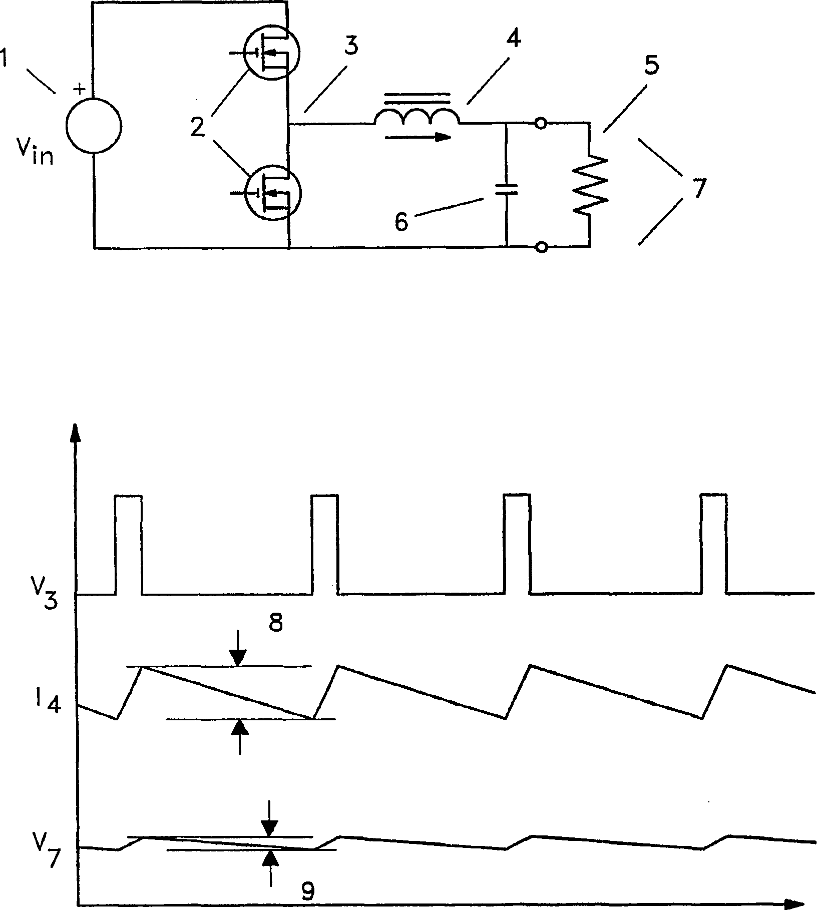
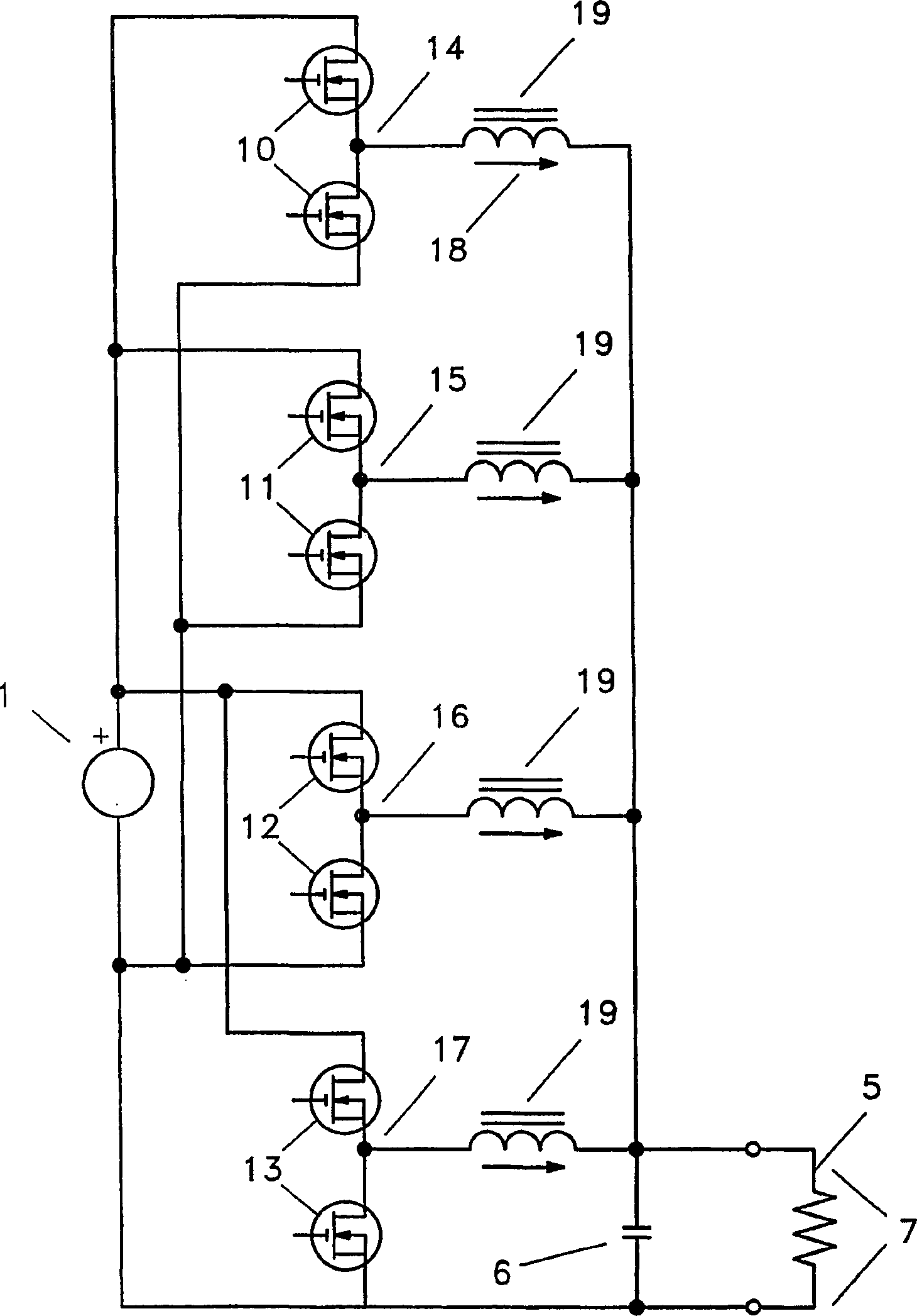
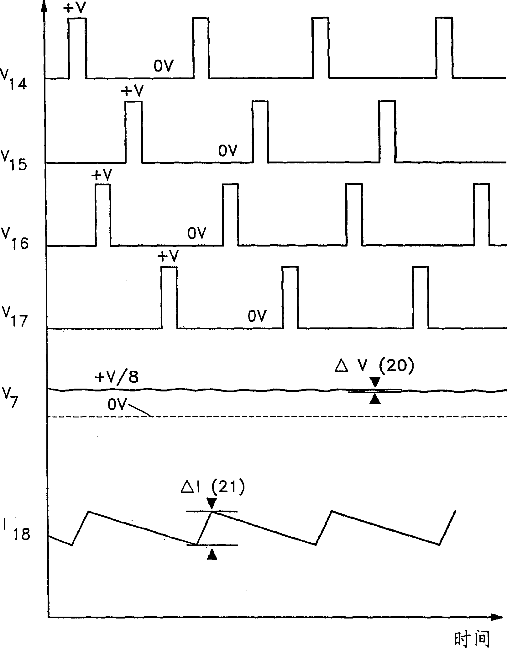
[0056] When generating a low regulated dc voltage from a higher voltage source, a so-called "buck" converter is often used. Such as figure 1 As shown in , this converter can be thought of as a simple circuit with the general four basic elements: two electronic switches, an inductor and a capacitor. If the output voltage is higher than the voltage drop across the diode, the lower electronic switch can be replaced ...


PUM


Abstract

Methods and circuitry for combining the outputs of multiphase power converters which greatly improves the transient response of the power conversion system are presented in a variety of embodiments. Transformers may be used to accomplish the combining function, and with properly phased and connected windings it is possible to achieve a great reduction in output ripple current and a simultaneous reduction in transistor ripple current, which give the designer freedom to reduce the value of the system output inductor, improving transient response.

Description

technical field [0001] The present invention relates to the field of powering low voltage, high current electronic equipment such as found in the computing field and will be described in detail below. The present invention is broadly applicable to situations in which various power absorbing loads may suddenly change their power absorbing characteristics (that is, the impedance may undergo rapid changes). The invention also applies if the loads are physically separated such that the voltage drop across the dynamic impedance of the power carrying conductors accounts for a substantial fraction of the voltage delivered to such loads. The invention may also be applicable to applications where design tradeoffs force a steady reduction in operating voltage. This situation can arise in telecommunications, radar systems, vehicle power systems, etc., as well as computing systems. Background technique [0002] The architecture of computing systems has undergone dramatic changes recen...

Claims


Application Information

Patent Timeline
IPC IPC(8): H02M7/21G06F1/26H02J1/00H02M1/088H02M3/155H02M3/158H02M3/28H02M3/335
CPCH02M3/158H02M1/088H02J2001/008G06F1/26H02J1/00H02J2001/002H02M2001/009H02M3/1584H02M3/335H02M3/33561H02J1/002H02J1/082H02M1/009H02M1/08
Inventor 罗伯特·M·波特肯尼迪·G·古罗夫阿纳托利·B·列杰涅夫
Owner ADVANCED ENERGY INDS
Why Eureka
Try Eureka