Thin-belt continuous casting method and apparatus

A continuous casting and thin strip technology, applied in the direction of metal rolling, etc., can solve the problems of thin strip continuous casting industrialization difficulties, difficult operation and sealing, complex equipment, etc., to reduce investment costs and maintenance costs, and improve surface cracks , The effect of flexible process control

Inactive Publication Date: 2004-02-04
BAOSHAN IRON & STEEL CO LTD
View PDF3 Cites 24 Cited by
  • Summary
  • Abstract
  • Description
  • Claims
  • Application Information

AI Technical Summary

Problems solved by technology

This brings difficulties to the industrialization of thin strip continuous casting
[0005] 2. Unstable quality
(2) During the production process, the process parameters such as casting speed and casting temperature may change according to the production situation
If the solidification end point is below the contact point of the twin rolls during thin strip continuous casting, breakout, shrinkage and shrinkage will occur in the cast strip; on the contrary, if the solidification end point is above the contact point of the twin rolls, the rolling force will be rapid Increased, the cast strip is rolled in the high-temperature molten two-phase zone, and the steel is basically in the high-temperature brittle zone, where longitudinal cracks easily occur. If the rolling force overloads the crystallization roll, it will stop, resulting in production stoppage and even molten steel Spills in the crystallization rollers, causing safety accidents
[0006] 3. Relatively low productivity
The control idea is to control the quality of the cast strip by controlling the temperature of the crystallization roll, that is, controlling the primary cooling; through the air cooling control of the direction of the crystallization roll body, the uniformity of the surface temperature of the crystallization roll is solved, and finally the purpose of controlling the quality of the cast strip is achieved. ; Moreover, the whole set of equipment is arranged in the direction of the roll body to control a series of gas mixing chambers, gas pipes and nozzles. The overall equipment is relatively complicated, especially in the position of the upper airtight chamber, which brings difficulties to operation and sealing; especially when the crystallization roll In the event of a steel spill, the system will be damaged

Method used


Image

  • Thin-belt continuous casting method and apparatus
  • Thin-belt continuous casting method and apparatus
  • Thin-belt continuous casting method and apparatus

Examples


Embodiment Construction

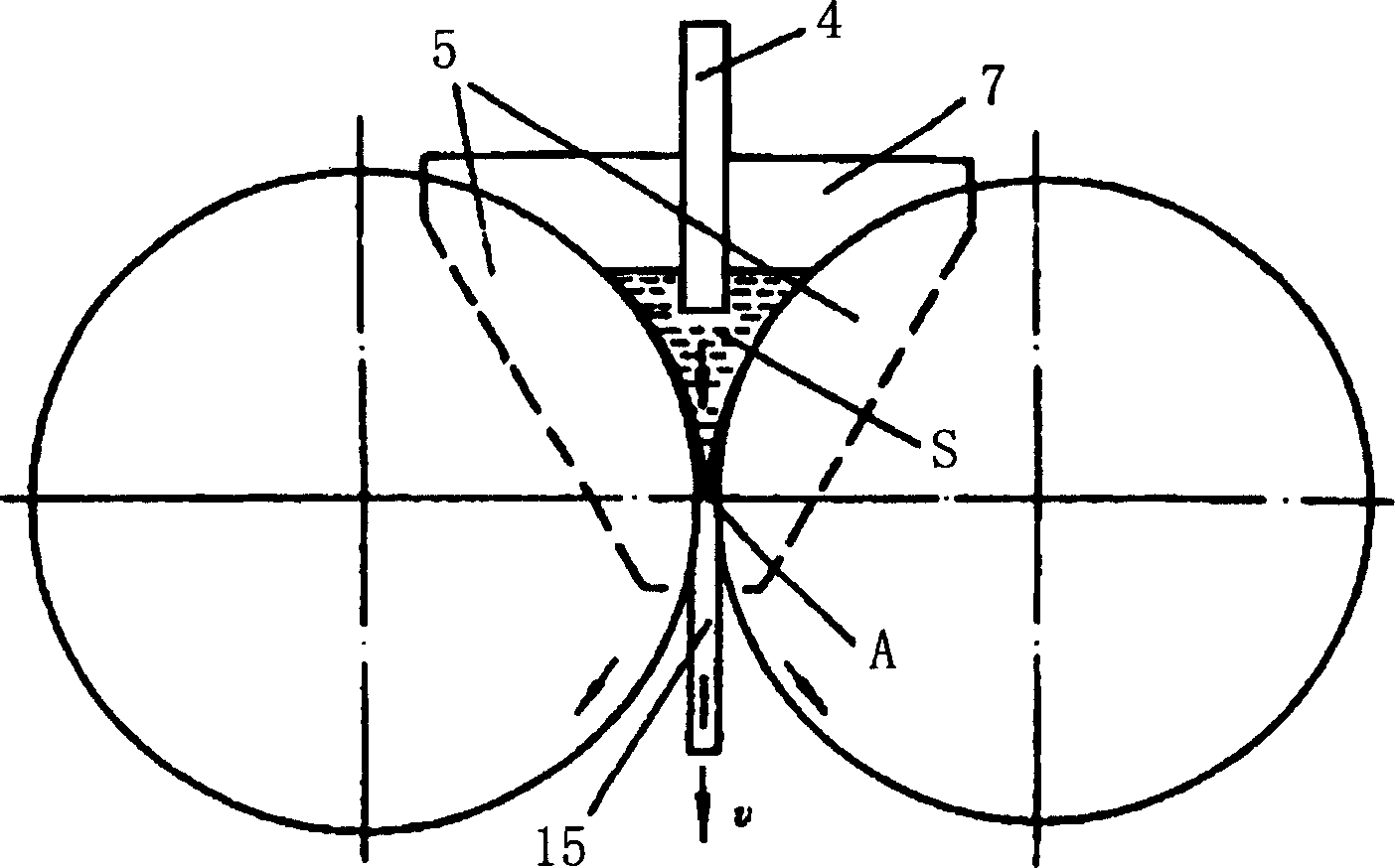
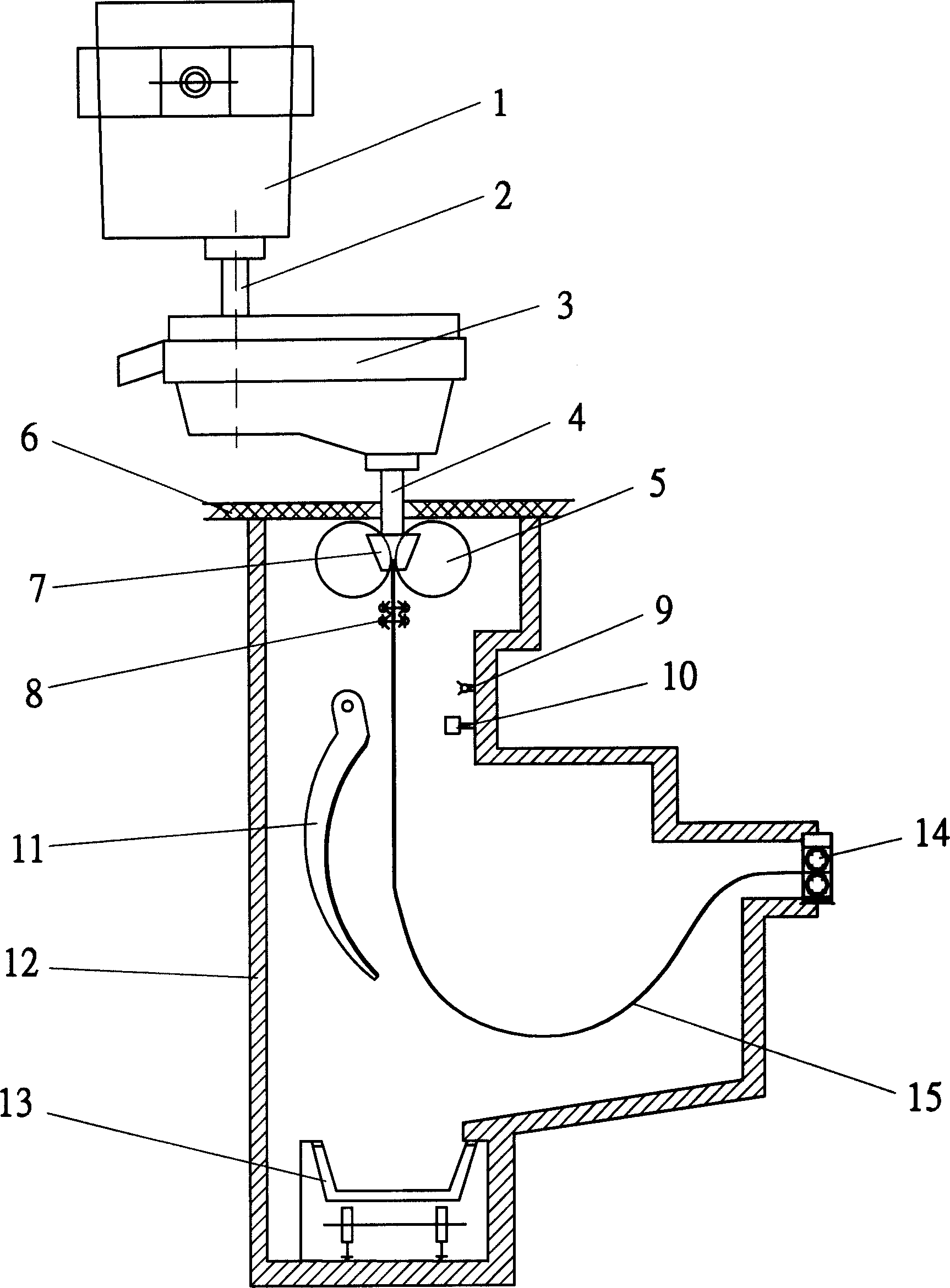
[0045] like figure 2 As shown, the molten steel S enters the molten pool formed by the rotating water-cooled crystallization roller 5 from the ladle 1 through the long nozzle 2, the tundish 3 and the submerged nozzle 4, and forms a casting belt 15 after being cooled by the water-cooled crystallization roller 5, and passes through the swing guide plate 11, The pinch roller 14 sends the cast strip 15 to hot rolling, and then through hot rolling, controlled cooling until coiling.

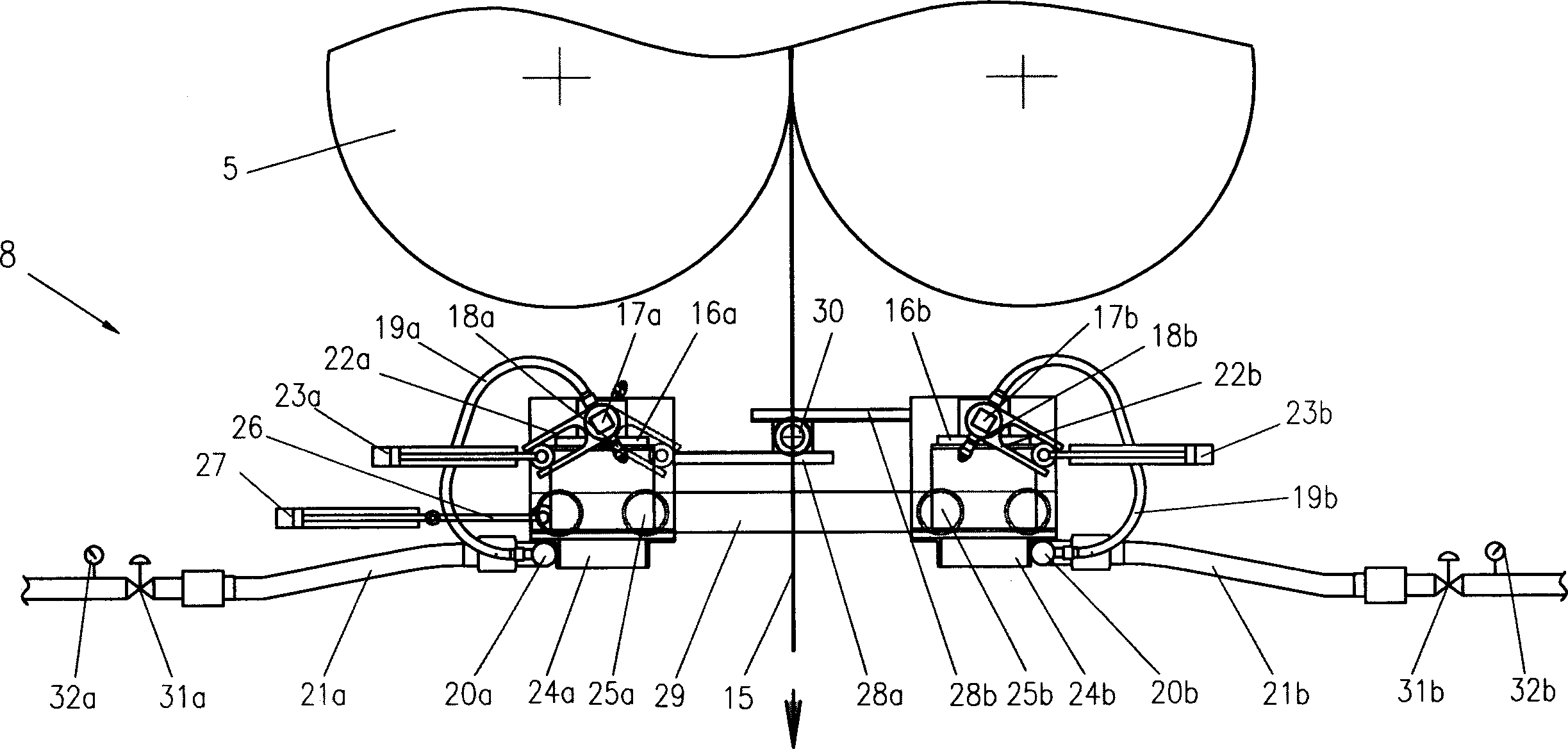
[0046] Since the temperature of the casting belt 15 reaches above 1300° C. at the place where the crystallization roller 5 exits, the high temperature strength of the casting belt 15 is very low. Cast belt 15 is prone to cracks or even breakouts at the exit under the effects of gravity, pinch roller 14 tension, etc. Therefore, in the present invention, by setting a control cooling device 8 at the outlet of the crystallization roller 5, different cooling processes are performed according to the high-t...


PUM

PropertyMeasurementUnit
lengthaaaaaaaaaa

Abstract

A conticasting technology for thin steel band includes such steps as filling molten steel in the molten bath formed by crystallizing rollers, cooling and slight rolling by crystallizing rollers, blowing gas onto both surfaces of cast band for forced cooling, hot rolling, controlled cooling and winding. Its apparatus is composed of two blowing mechanisms, connecting-rod driver unit and synchronizing unit. Its advantages are high quality of product and high productivity.

Description

technical field [0001] The invention relates to thin strip continuous casting process and equipment technology, in particular to continuous casting thin strip cooling control and device. Background technique [0002] Thin strip continuous casting is a new process of directly casting molten steel into 1-5mm thin strips. At present, the basic technological process of thin strip continuous casting is: crystallization roll thin strip continuous casting machine (twin roll, single roll, wheel belt type) - airtight chamber - looper - pinch - hot rolling (single rack or two racks or no ) - controlled cooling - coiling. [0003] At present, the main problems of this process are: [0004] 1. It is difficult to control the end point of solidification. In the traditional continuous casting process, the continuous casting slab is completely solidified after passing through the crystallizer, secondary cooling, and air cooling zone. The length of the liquid core is 23000-30000mm. The in...

Claims


Application Information

Patent Timeline
Patent Type & Authority Applications(China)
IPC IPC(8): B21B1/46B22D11/06
Inventor 于艳方园孟昭圭樊俊飞
Owner BAOSHAN IRON & STEEL CO LTD
Why Eureka
Try Eureka