Ion implanted composite coating film apparatus

A composite coating and ion implantation technology, applied in the field of ion implantation composite coating equipment and multi-functional composite coating equipment, can solve problems such as single function, and achieve the effect of reducing equipment manufacturing cost, novel equipment design, and reasonable and compact structure

Inactive Publication Date: 2004-02-04
SHANGHAI JIAO TONG UNIV +1
View PDF1 Cites 26 Cited by
  • Summary
  • Abstract
  • Description
  • Claims
  • Application Information

AI Technical Summary

Problems solved by technology

[0004] The purpose of the present invention is to overcome the single-function shortcoming of most current coating equipment, and provide a multi-functional ion implantation composite coating equipment, which integrates several surface modification technologies of materials, and the equipment is novel in design and reasonable in struct

Method used


Image

  • Ion implanted composite coating film apparatus
  • Ion implanted composite coating film apparatus
  • Ion implanted composite coating film apparatus

Examples


Embodiment Construction

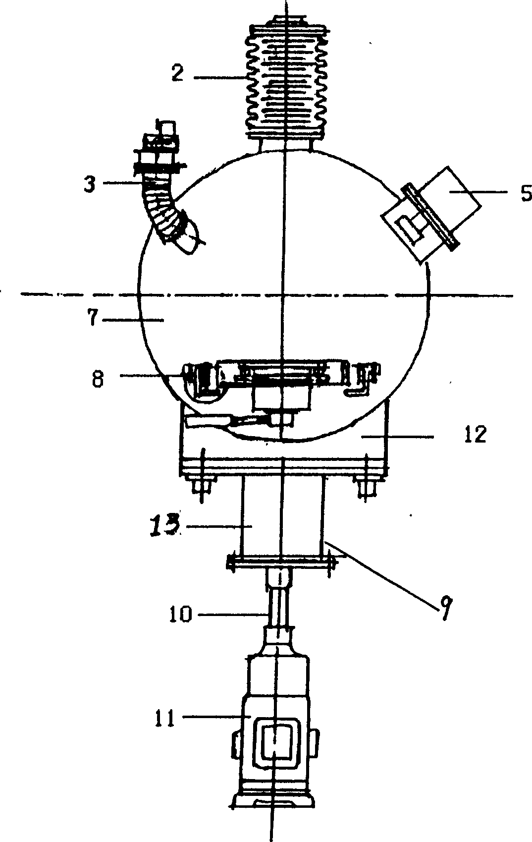
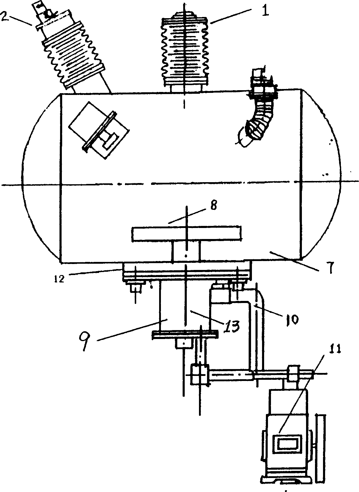
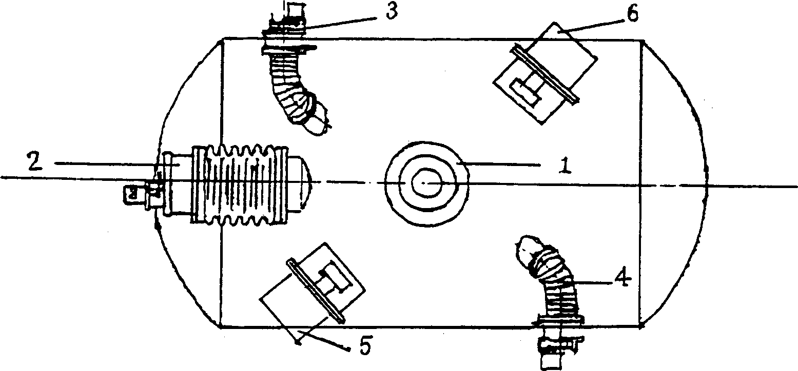
[0018] Such as figure 1 , figure 2 and image 3 As shown, the present invention includes: a gas ion source 1, a metal ion source 2, two DC magnetic filtered arc ion plating sources 3 and 4, a DC magnetron sputtering target source 5, an intermediate frequency pulse magnetron sputtering target source 6, a vacuum Chamber 7, multi-purpose sample stage 8 and vacuum pumping system 9. Its connection mode is: gas ion source 1, metal ion source 2, DC magnetron sputtering target source 5, intermediate frequency pulse magnetron sputtering target source 6, and two sets of DC magnetic filter arc ion plating sources 3 and 4 shared by six sources A vacuum chamber 7, and fixed on the shell of the composite coating machine, the gas ion source 1 is vertically located in the middle of the upper part of the vacuum chamber 7, and the metal ion source 2 is located on one side of the gas ion source 1, and is obliquely inserted in the upper part of the vacuum chamber 7. The center line is 62° to ...


PUM


Abstract

A composite ion implantation plating equipment is composed of 6 ion source (gas ion source, metal ion source, DC magnetically controlled sputter target source, MF-pulse magnetically controlled sputter target source and two DC magnetic filter arc ion source), a vacuum chamber containing a multi-purpose bench, and a vacuumizing system for said vacuum chamber.

Description

technical field [0001] The invention relates to a multifunctional composite coating equipment for material surface modification, in particular to an ion implantation composite coating equipment, which belongs to the technical field of coating. Background technique [0002] As the requirements for the surface modification layer of materials are getting higher and higher, it is often difficult for a single material surface modification layer to meet the requirements of some occasions. Therefore, the composite surface that integrates the advantages of two or more surface modification methods Modification technology came into being. To realize composite surface modification of materials, corresponding composite coating equipment is the key. If you want to combine ion implantation with PVD or CVD, one method is to put the workpiece in ion implantation equipment for processing, then take it out and put it in PVD or CVD equipment for processing, and then put it in ion implantation...

Claims


Application Information

Patent Timeline
IPC IPC(8): C23C14/48
Inventor 蔡珣童洪辉陈庆川蒲世豪赵军陈秋龙刘佑铭
Owner SHANGHAI JIAO TONG UNIV
Why Eureka
Try Eureka