Yarn layer breadth-determining spinning mechanism of warper

A winding mechanism and width-fixing technology, which is applied in the textile field, can solve problems such as disordered yarn stacking order, unfixable width, troublesome weaving beam rewinding, etc., so as to achieve regular and orderly stacking of yarn layers and wide warping width. Controllable, good unwinding effect

Inactive Publication Date: 2004-03-17
DONGHUA UNIV
View PDF0 Cites 4 Cited by
  • Summary
  • Abstract
  • Description
  • Claims
  • Application Information

AI Technical Summary

Problems solved by technology

Its working process is that the yarn 1 is pulled out from the bobbin 2, passes through the yarn guide plate 3, the tensioner 4, the tension ring 5, bypasses the support disc 6, and is wound onto the drum A by the yarn winding finger 71 of the yarn winding rod 7. Inclined block 8 until it slides on 16 toothed conveyor belts 9 distributed along the circumference of drum A, then toothed conveyor belt 9 carries yarn 1 and moves to the right end to form a yarn layer. After the number of turns n' (n' is the quotient of the warping length of the weaving beam divided by the circumference of the cylinder), the toothed conveyor belt 9 will move a certain distance (the center distance between the two warp yarns on the weaving beam). This traditional yarn layer winding The method is called the fixed width winding method. In the actual winding process, the regular winding of the yarn layer cannot be realized, which makes the collapse of the warp yarn layer very serious. The order of yarn stacking is disordered, and the unwinding of the yarn on the cylinder is hindered when the weaving beam is wound, and the warping effect will be poor. Therefore, the warping length is usually only 30 to 40 meters
[0003] In order to increase the warping length, there is a method of regular winding of the yarn layer - direct winding method (Direct Winding), such as figure 2 As shown in the figure, the inclined block 8 is fixed on the drum A, and it is used as a stable support for the yarn layer. As the winding progresses, the yarn winding finger 71, the pin shaft 25, and the yarn guide plate 26 are constantly moving to the right. At the same time, the yarn guide plate 25 rotates and swings around the pin shaft 26 to discharge the yarn. The stacking structure of the yarn layer is relatively regular, and the unwinding effect is good, which is conducive to increasing the warping length. However, this method cannot be warped according to the process design. Yarns are arranged according to the density, so it is not possible to fix the width, which brings great troubles to the rewinding of the weaving beam. At the same time, its structure is complex and occupies a large area, so it is not easy to transplant and modify on the existing sample warping machine.

Method used


Image

  • Yarn layer breadth-determining spinning mechanism of warper
  • Yarn layer breadth-determining spinning mechanism of warper
  • Yarn layer breadth-determining spinning mechanism of warper

Examples


Embodiment Construction

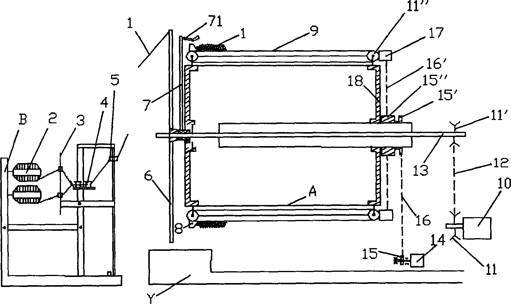
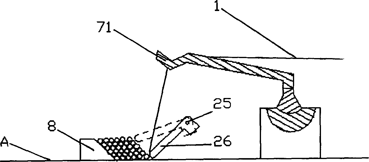
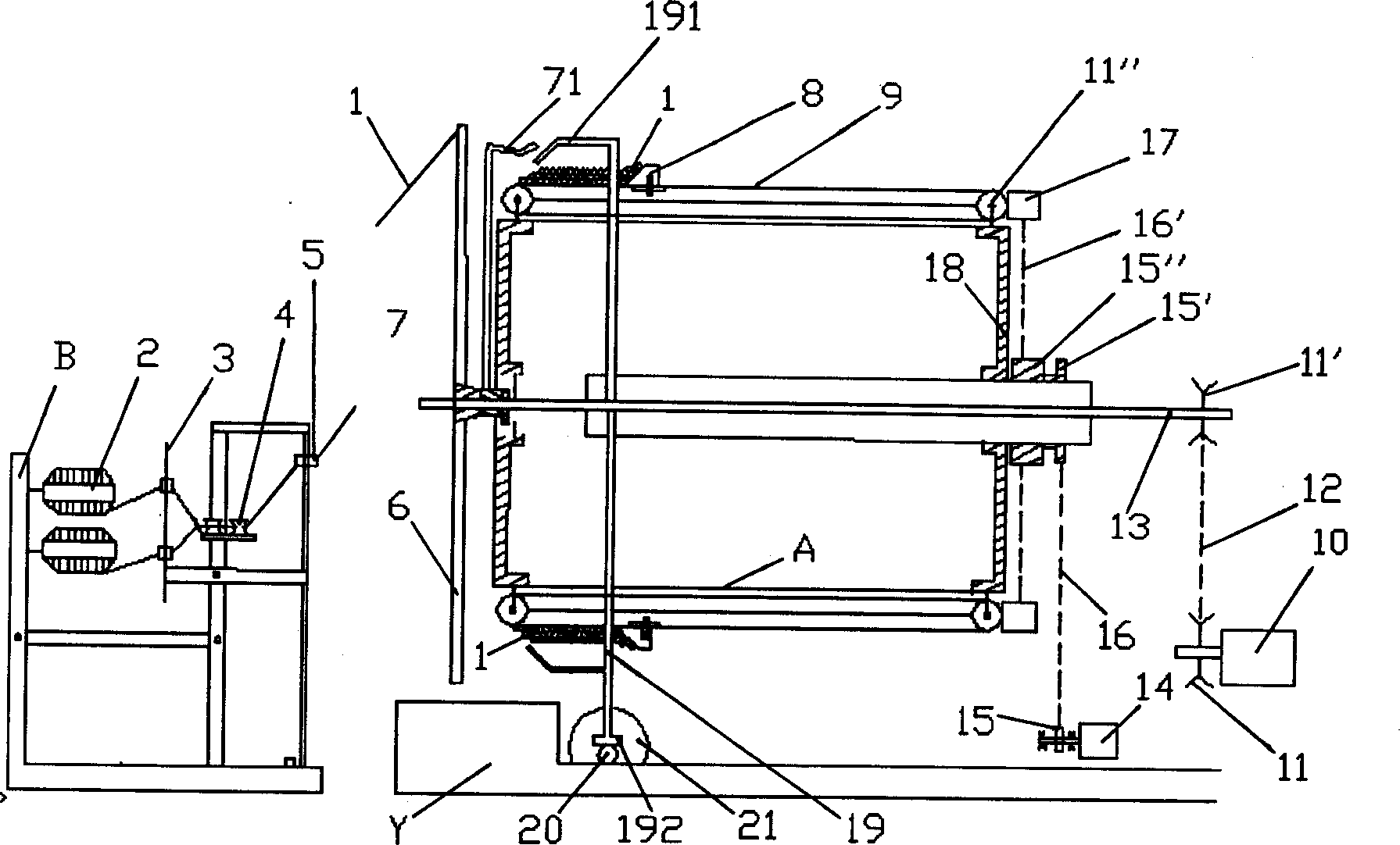
[0023] A fixed and regular winding mechanism for a sample warping machine yarn layer, which includes a creel B, a guide plate 3, a tension disc 4, a tension ring 5, a support disc 6, a yarn winding rod 7, a yarn winding finger 71, and an inclined block 8. Toothed conveyor belt 9, AC variable frequency motor 10, toothed wheel 11, 11', toothed belt 12, drive shaft 13, servo motor 14, sprocket 15, 15', 15", chain 16, 16', gear Box 17, wheel spoke 18, cylinder A, base Y, is characterized in that it also comprises guide bar frame 19, and its inner wall is the guide bar 191 of uniform distribution, and its outer circle has three tooth racks 192 stretched out at three places on the left and right , it meshes with the three left and right gears 20 through the three left and right racks 192, and the three left and right gears 20 are respectively fixed on the shaft ends of the three left and right stepper motors 21 and meshed with the three left and right racks 192. The three stepping m...


PUM


Abstract

The present invention discloses a constant size profiling winding device for the yarn layer of sample piece beaming machine features that it also includes a guide rod frame on the inner wall of whichare guide rods in uniform distribution, three rack bars are extended on the left bottom of its outer ring, and three toothed gears and three stepping motors are arranged on the left bottom position. The invention accomplishes constant size profiling yarn discharging method by simple structure.

Description

Technical field: [0001] The invention belongs to the field of textiles, and relates to a mechanism for fixed and regular winding of yarn layers of a sample warping machine. Background technique: [0002] With the increasingly fierce market competition and the variety of textiles and the rapid update, the sample warping machine is gradually favored by textile enterprises, because it simplifies the original processing with large yarn consumption, long process flow and slow response speed. link, so the machine is a powerful tool for new product development and fabric trial weaving, figure 1 It is a traditional fixed creel warping machine. The AC variable frequency motor 10 drives the driving shaft 13 to rotate through the toothed wheel 11, the toothed belt 12, and the toothed wheel 11', and then the driving shaft 13 rotates to drive the yarn winding. Rod 7 rotates, is driven by servomotor 14 through sprocket 15, chain 16, sprocket 15 ', sprocket 15 ", chain 16 ', gear box 17 a...

Claims


Application Information

Patent Timeline
Patent Type & Authority Applications(China)
IPC IPC(8): D02H3/00
Inventor 夏飞朱苏康
Owner DONGHUA UNIV
Why Eureka
Try Eureka