Alloy type temp fuse and wire for temp fuse element

A technology of alloy type and fuse, which is applied in the direction of electrical components, fuse manufacturing, metal processing equipment, etc., can solve the problem of not being able to fully meet the working temperature of 130 ° C ~ 170 ° C, and achieve high capacity and reduce resistance efficiency, miniaturization

Inactive Publication Date: 2004-05-05
UCHIHASHI ESTEC
View PDF10 Cites 10 Cited by
  • Summary
  • Abstract
  • Description
  • Claims
  • Application Information

AI Technical Summary

Problems solved by technology

[0017] However, none of the operating temperatures is lower than 130°C, and the above-mentioned necessary conditions for the operating temperature of 130 to 170°C cannot be satisfied.
[0018] Furthermore, it is also known that alloys with Sn0.5-10%, Sn33-43%, and Bi47-66.5% have an operating temperature of 125°C to 135°C (JP-A-2001-266723), for the range of more than 135°C to 170°C , can not fully meet the above-mentioned necessary conditions for the working temperature of 130 ° C ~ 170 ° C

Method used


Image

  • Alloy type temp fuse and wire for temp fuse element
  • Alloy type temp fuse and wire for temp fuse element
  • Alloy type temp fuse and wire for temp fuse element

Examples


Embodiment 1

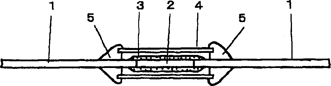
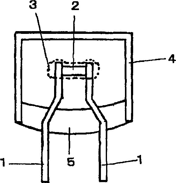
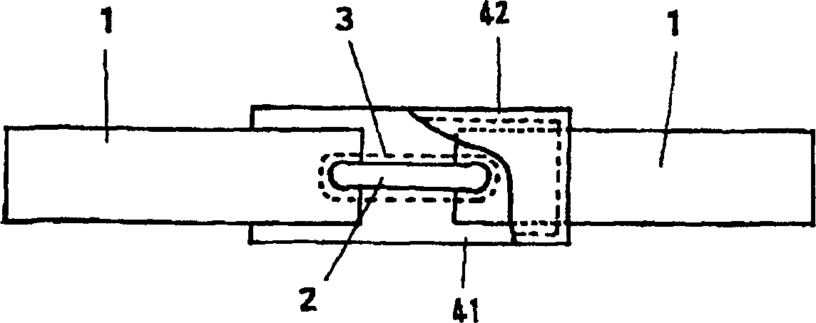
[0078] The alloy-type temperature fuse of the cylindrical shell type has a fuse element whose composition is 48% Sn, 2% In, and Bi as the remainder.

[0079] It works in the above-mentioned overload charging, but it cannot work with the destruction. Regarding the insulation stability after this work, the lead conductors can withstand 2×rated voltage (500V) for 1 minute, and the lead conductor-outside of the cylindrical shell can withstand 2×rated voltage +1000V (1500V) for 1 minute, And when the DC voltage value is 2× rated voltage (500V), the insulation resistance between the lead conductors is 0.2MΩ or more, and the insulation resistance between the lead conductors and the outer surface of the cylindrical case is 0.2MΩ or more, then the insulation stability is ○.

[0080] When the temperature fuse is working, the temperature of the fuse element is 135°C, and the liquidus temperature of the fuse element is 152°C (the element temperature is 17°C lower than the liquidus tempera...

Embodiment 2~5

[0085] For Example 1, except that the amount of Sn is changed as shown in Table 1, and the amount of Bi corresponding to the device is also changed, it is considered to be the same as that of Example 1.

[0086] In either example, similarly to Example 1, no damage occurred even when operating under overload charging, and the insulation stability after overload operation was evaluated as ◯.

[0087] And, obviously, in which embodiment, the element temperature during operation is also lower than the liquidus temperature (11°C-13°C lower), and the fuse element is cut off in the solid-liquid coexistence region. The reason why the insulation stability of the temperature fuse after operation is ○ without causing damage during overload charging is presumed to be because the fuse element is cut off in a wide solid-liquid coexistence area, because the operation There are very few arcs shortly thereafter, and it is difficult to cause a local and rapid temperature rise, so the pressure r...

Embodiment 2   Embodiment 3   Embodiment 4

[0091] Example 2 Example 3 Example 4 Example 5

[0092] Sn(%) 44 53 62 70

[0093] In(%) 2 2 2 2

[0094] Bi(%) remaining remaining remaining remaining

[0095] Disruptive while working None None None None

[0096] Insulation stability after operation ○ ○ ○ ○

[0097] Liquidus temperature (°C) 144 156 167 178

[0098] Component temperature at work (°C) 132±1 143±2 152±3 162±3

[0099] Resistivity (μΩ·cm) 36 31 27 23

[0100] Wire drawing property ○ ○ ○ ○


PUM

PropertyMeasurementUnit
thicknessaaaaaaaaaa
electrical resistanceaaaaaaaaaa

Abstract

An alloy type thermal fuse is provided in which a ternary Sn-In-Bi alloy is used, the operating temperature belongs to the range of 130 to 170 DEG C., the overload characteristic and the dielectric breakdown characteristic are excellent, the insulation stability after an operation can be sufficiently ensured, and thinning of a fuse element can be easily realized. A fuse element having an alloy composition in which Sn is larger than 43% and 70% or smaller, In is 0.5% or higher and 10% or lower, and a balance is Bi is used.

Description

technical field [0001] The invention relates to an alloy-type temperature fuse with an operating temperature of about 130° C. to 170° C. and a wire material for a temperature fuse element. Background technique [0002] General-purpose alloy type thermal fuses are used as thermal protection devices for electrical equipment or circuit components, such as semiconductor devices, capacitors, resistors, etc. [0003] The alloy-type temperature fuse is made of an alloy with a specified melting point as a fuse element, the fuse element is welded between a pair of lead conductors, a flux is applied to the fuse element, and the flux is coated with an insulator to seal the fuse element. The composition of silk elements. [0004] The mechanism of this alloy type thermal fuse is as follows. [0005] Alloy type thermal fuses are arranged in thermal contact on the electrical equipment or a large number of components that want to be protected. Once the electrical equipment or circuit com...

Claims


Application Information

Patent Timeline
Patent Type & Authority Applications(China)
IPC IPC(8): C22C12/00B23K35/26C22C13/02C22C30/04H01H37/76H01H69/02
CPCC22C13/02B23K35/262H01H2037/768C22C30/04H01H37/761C22C12/00
Inventor 田中嘉明猿渡利章
Owner UCHIHASHI ESTEC
Why Eureka
Try Eureka