Lithographic printing projector containing secondary electronic clear cell

A technology of lithographic printing and projection devices, which is applied in the direction of photoplate-making process exposure devices, electrical components, patterned surface photoplate-making processes, etc., to achieve the effect of reducing the chance of pollution

Inactive Publication Date: 2004-05-19
ASML NETHERLANDS BV
View PDF12 Cites 1 Cited by
  • Summary
  • Abstract
  • Description
  • Claims
  • Application Information

AI Technical Summary

Problems solved by technology

[0022] Another issue is how to monitor the amount of radiation from the source and the amount of contamination that collects on the optics

Method used


Image

  • Lithographic printing projector containing secondary electronic clear cell
  • Lithographic printing projector containing secondary electronic clear cell
  • Lithographic printing projector containing secondary electronic clear cell

Examples


Embodiment Construction

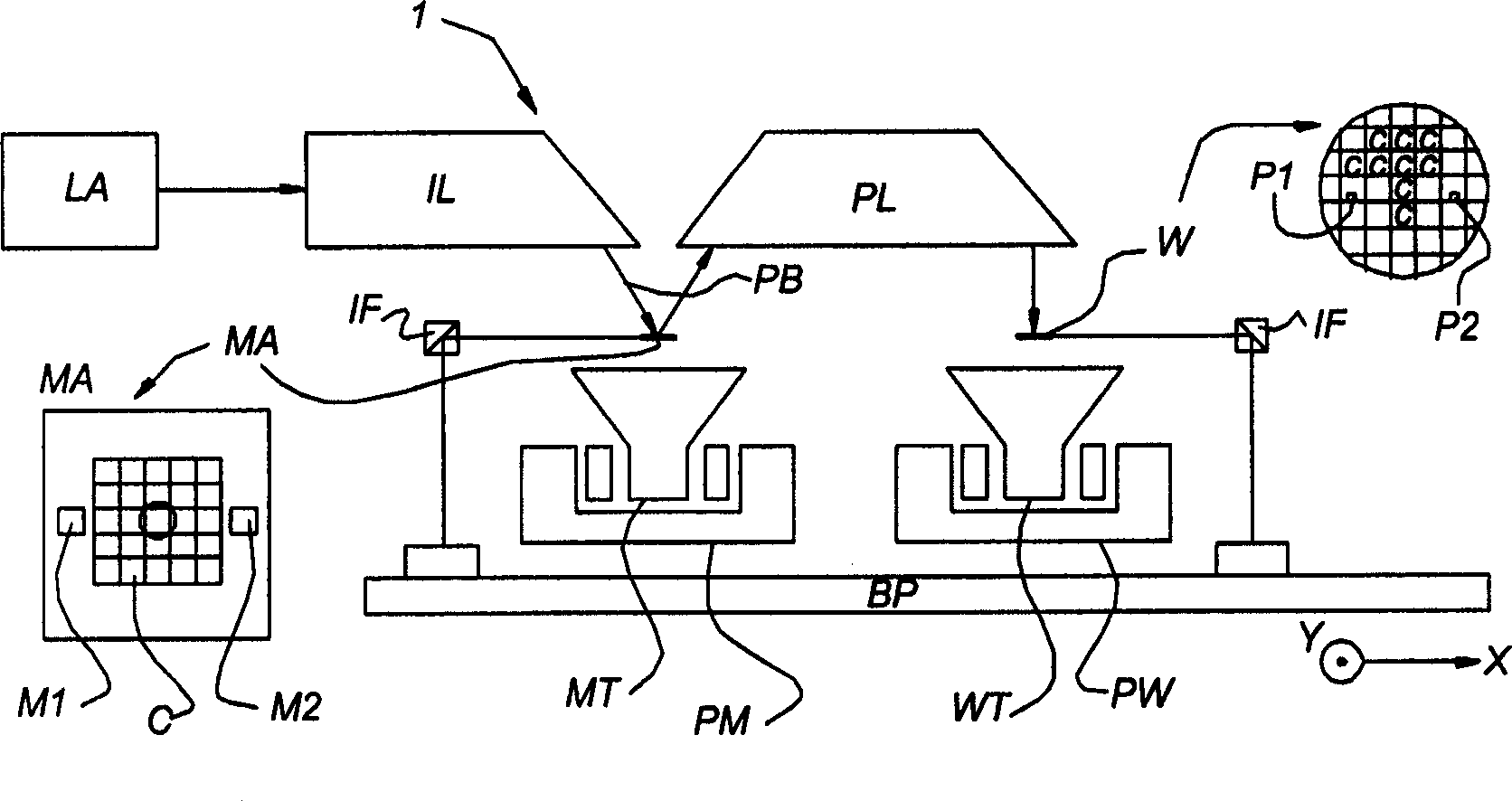
[0046] figure 1 It is a schematic representation of a lithographic projection device according to a specific embodiment of the present invention. The unit includes:

[0047] a radiation system IL for providing a radiation projection beam PB (e.g. EUV radiation) having 11-14 nm, in this particular example, the radiation system also includes a radiation source LA;

[0048] A first target table (mask table) MT, provided with a mask holder for fixing a mask MA (e.g. a reticle), and with first positioning means PM for precise positioning of the mask relative to the target PL connect;

[0049] A second target stage (substrate table) WT, provided with a substrate holder for holding a substrate W (e.g. a resist-coated silicon wafer), is connected to a second positioning device for precise positioning of the substrate relative to the target PL ;

[0050] A projection system ("lens") PL is used to image the radiation portion of the mask MA onto a target portion C of a substrate W (...


PUM


Abstract

A lithographic projection apparatus is provided wherein an object situated in a pulsed beam of radiation has an electrode in its vicinity and a voltage source connected either to the electrode or to the object. This configuration can provide a negative voltage pulse to the object relative to the electrode. The beam of radiation and the voltage pulse from the voltage source are provided in phase or out of phase. In this way, the object is shielded against secondary electrons generated by radiation beam illumination.

Description

field of invention [0001] The invention relates to a lithographic projection device, comprising: [0002] A radiation system forming a radiation projection beam by radiation emitted from a radiation source, [0003] a support structure configured to support patterning means radiated by the projection beam for patterning the projection beam, [0004] constituted as a substrate platform supporting a substrate, [0005] for a projection system constructed and arranged to image an irradiated portion of a patterning member onto a target portion of a substrate, and [0006] Shielding means for generating an electromagnetic field to prevent the incidence of secondary electrons formed during irradiation on the object to be shielded, said shielding means comprising: [0007] an electrode near the target, and [0008] A voltage source connected to the target and / or electrodes for providing a voltage between the target and the electrodes. Background technique [0009] In EP 1 182 ...

Claims


Application Information

Patent Timeline
Patent Type & Authority Applications(China)
IPC IPC(8): G03F7/20H01L21/027
CPCG03F7/70233G03F7/70983G03F7/702H01L21/027
Inventor R·库尔特L·P·巴克F·J·P·舒尔曼斯
Owner ASML NETHERLANDS BV
Why Eureka
Try Eureka