High-tension transformer

A high-voltage transformer and iron core technology, applied in the field of high-voltage transformers, can solve the problems of reducing distributed capacitance, differential high-voltage output characteristics, etc., and achieve the effects of increasing withstand voltage, minimizing harmonics, and reducing processing steps

Inactive Publication Date: 2004-05-19
MURATA MFG CO LTD
View PDF1 Cites 6 Cited by
  • Summary
  • Abstract
  • Description
  • Claims
  • Application Information

AI Technical Summary

Problems solved by technology

Also, in this bobbin, the secondary coil generates pulses with the same amplitude as in conventional bobbins, failing to reduce the distributed capacitance
As a result, the bobbin exhibits poor high-voltage output characteristics such as load characteristics and frequency characteristics, etc.

Method used


Image

  • High-tension transformer
  • High-tension transformer
  • High-tension transformer

Examples


Embodiment Construction

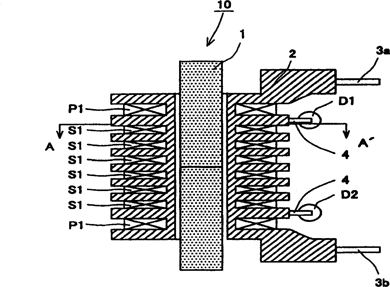
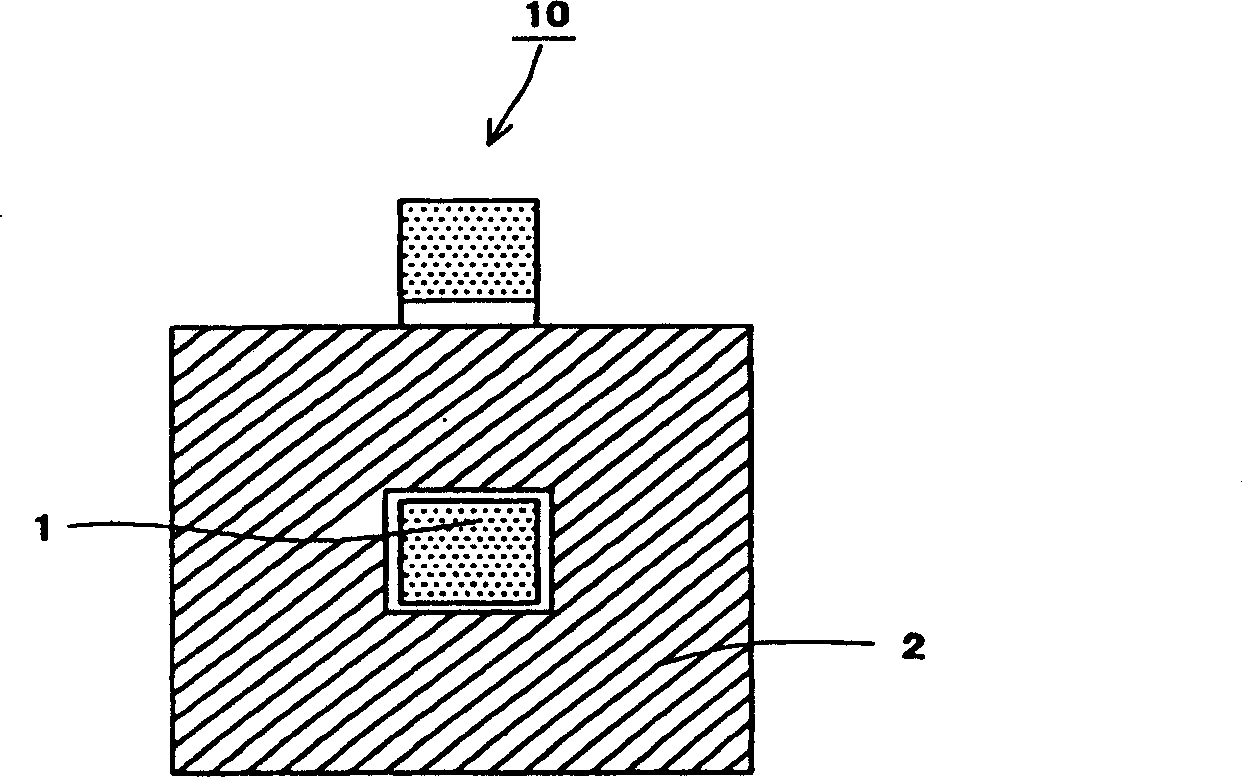
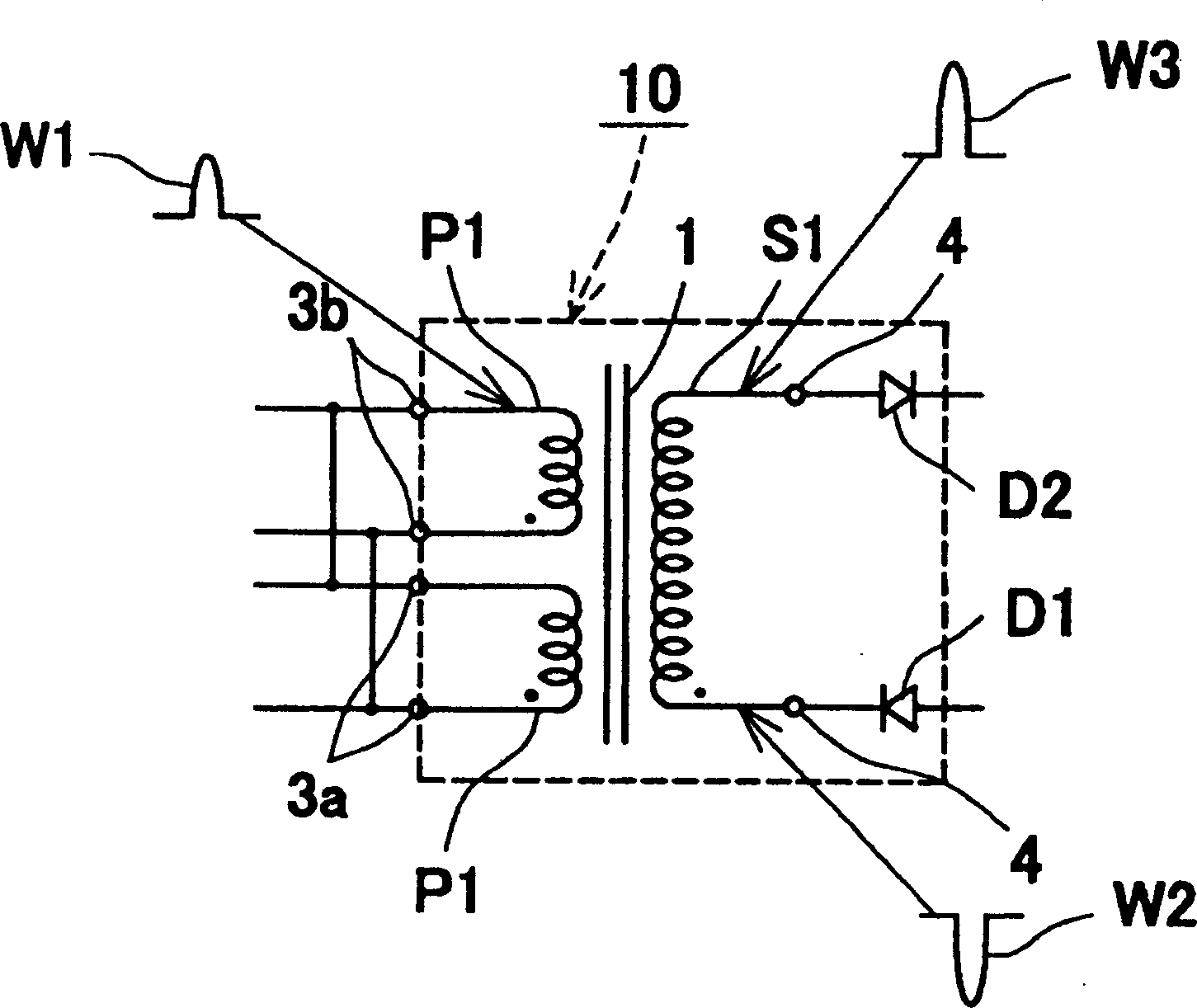
[0019] Now, will refer to Figure 1A , 1B and figure 2 , the first preferred embodiment of the present invention will be described. Figure 1A is the vertical cross-sectional view of the high-voltage transformer; Figure 1B is along Figure 1A The horizontal section obtained by the line A-A' in ; and figure 2 is a circuit diagram showing pulses generated by a high voltage transformer. refer to Figure 1A , 1B and figure 2 , the high voltage transformer 10 includes a bobbin 2 supporting an iron core 1 at the center thereof. For example, the core 1 is a horseshoe ferrite having a substantially square cross-section of approximately 4mm by 4mm. For example, the bobbin 2 is made of polybutylene terephthalate (PBT). The bobbin 2 has a hole for receiving the core 1 . The holes have a substantially square horizontal cross-section and a vertical cross-section that is the same throughout its length. For example, the bobbin 2 has nine flanges arranged along the central axi...


PUM


Abstract

A high-voltage transformer includes a bobbin that holds a core at its center. This bobbin has eight winding grooves arrayed along the central axis of the core. A primary coil is wound around each of two outermost winding grooves with a predetermined number of turns. A secondary coil is wound around the six winding grooves near the center with a predetermined number of turns, which are distributed among these winding grooves. The cathode of a diode is connected through a terminal to one end of the secondary coil where the winding starts, while the anode of another diode is connected through another terminal to the other end of the secondary coil where winding ends.

Description

technical field [0001] The present invention relates to high voltage transformers. Background technique [0002] Typically, copiers and printers use high voltage power supplies. These devices include high-voltage transformers with high-voltage outputs on the order of 10KV or more DC. [0003] For example, Japanese Patent No. 3182799 discloses this type of high voltage transformer. The high voltage transformer includes a transformer part and a voltage doubler-rectifier circuit part. Figure 4A is a sectional view showing a bobbin of a transformer portion. Figure 4B is a circuit diagram showing pulses generated by a high voltage transformer. refer to Figure 4A , the primary coil bobbin 21 has a hole for accommodating an iron core in its center and two flanges arranged along the central axis. These two flanges form the winding groove 22 . One of the two flanges has two terminals 23 . A concentric secondary coil bobbin 24 surrounds the primary coil bobbin 21 . The secon...

Claims


Application Information

Patent Timeline
Patent Type & Authority Applications(China)
IPC IPC(8): H01F27/28H01F5/02H01F27/26H01F27/30H01F27/32H01F27/40H01F30/00H01F38/42
CPCH01F27/306H01F27/266H01F27/325H01F5/02H01F27/40H01F38/42
Inventor 永井唯夫才田保信铃木俊彦
Owner MURATA MFG CO LTD
Why Eureka
Try Eureka