Heating roller, image heating apparatus, and image forming apparatus

A heating device and heating roller technology, applied in the field of heating rollers, can solve the problems of low mechanical durability of the heat generating layer, increase of excitation circuit cost, increase of preheating time, etc.

Inactive Publication Date: 2004-06-09
PANASONIC CORP
View PDF0 Cites 15 Cited by
  • Summary
  • Abstract
  • Description
  • Claims
  • Application Information

AI Technical Summary

Problems solved by technology

However, in order to reduce the skin depth, a higher frequency current is required to be applied, thereby causing problems such as increased cost of the excitation circuit and increased leakage of electromagnetic wave noise
[0012] In addition, since the heat generated layer passes through the extrusion roll (such as the attached Figure 14 Squeeze roller 827 and attached Figure 15 The shown outer squeeze roll 930) is repeatedly deformed in the nip portion, and in the case of forming the heat generating layer by nickel electroforming, there is a problem that the mechanical durability of the heat generating layer is low
In addition, in the case where the heat generating layer is formed of stainless steel, although the durability is improved, there arises a problem that the warm-up time increases

Method used


Image

  • Heating roller, image heating apparatus, and image forming apparatus
  • Heating roller, image heating apparatus, and image forming apparatus
  • Heating roller, image heating apparatus, and image forming apparatus

Examples


Embodiment I

[0035] attached Figure 5 Shown is a cross-sectional view of an example of an image forming apparatus according to the present invention in which an image heating device is used as a fixing device. The image heating device installed in the image forming apparatus according to Embodiment 1 is an electromagnetic induction heating device of a roll heating type. The following description is directed to the structure and operation of such a device.

[0036] Reference numeral 1 denotes an electrophotographic photoreceptor (hereinafter referred to as "photosensitive drum"). While the photosensitive drum 1 is driven at a predetermined peripheral speed in the direction indicated by the arrow, the surface of the photosensitive drum 1 is uniformly negatively charged by the charger 2 to reach a predetermined dark potential V0.

[0037] Reference numeral 3 denotes a laser beam scanner that outputs a time-series electrical digital pixel signal according to image information input from a h...

Embodiment I-1

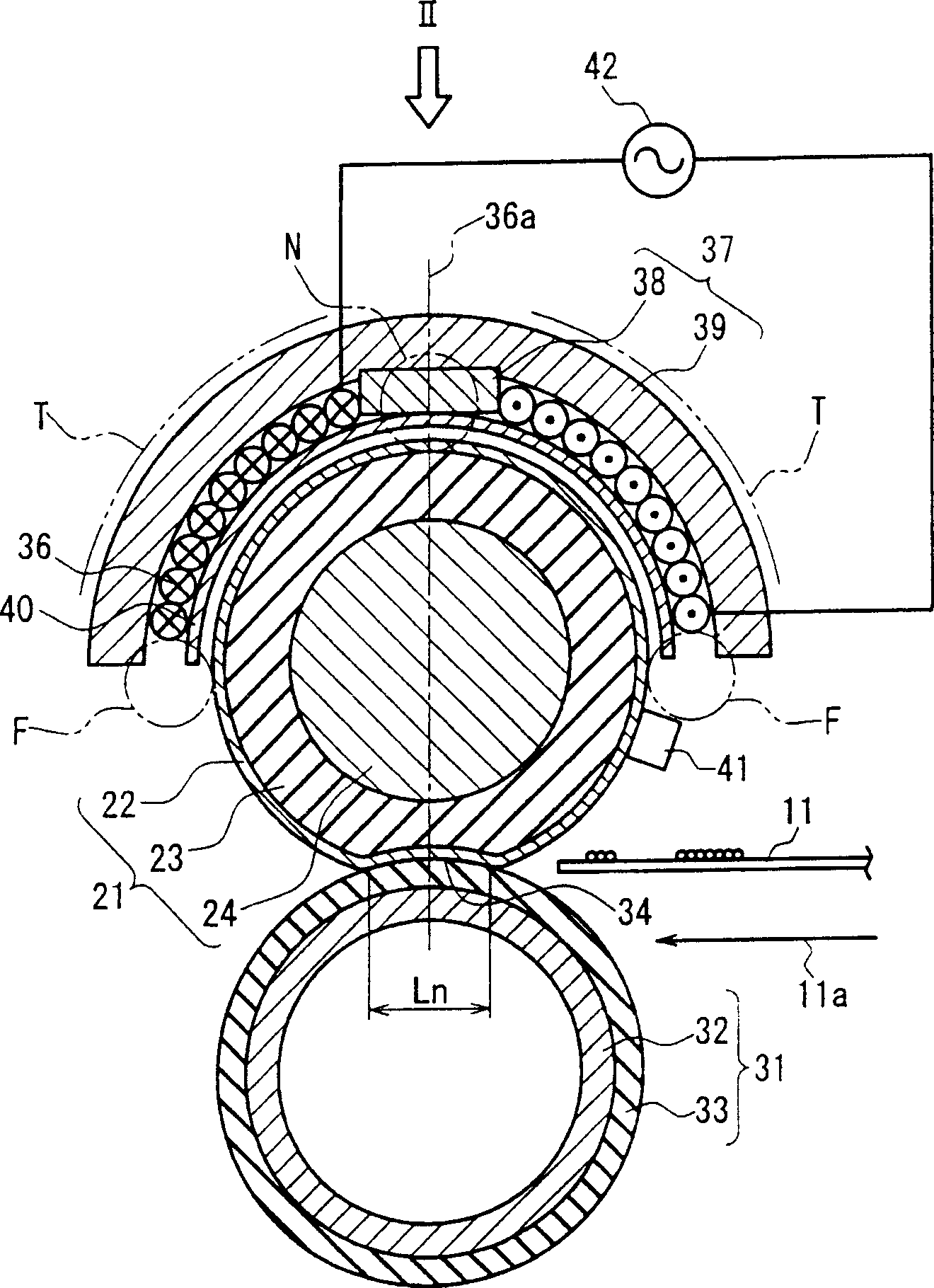
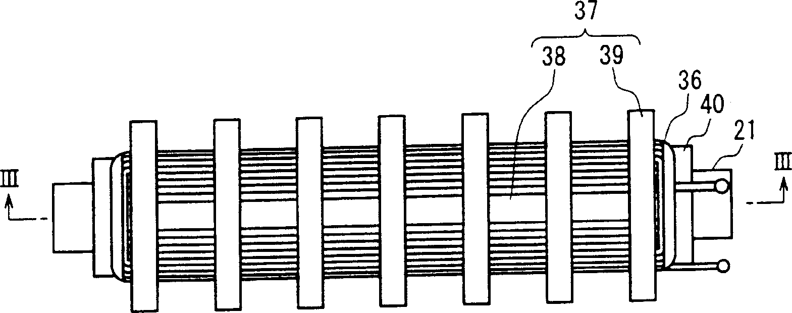
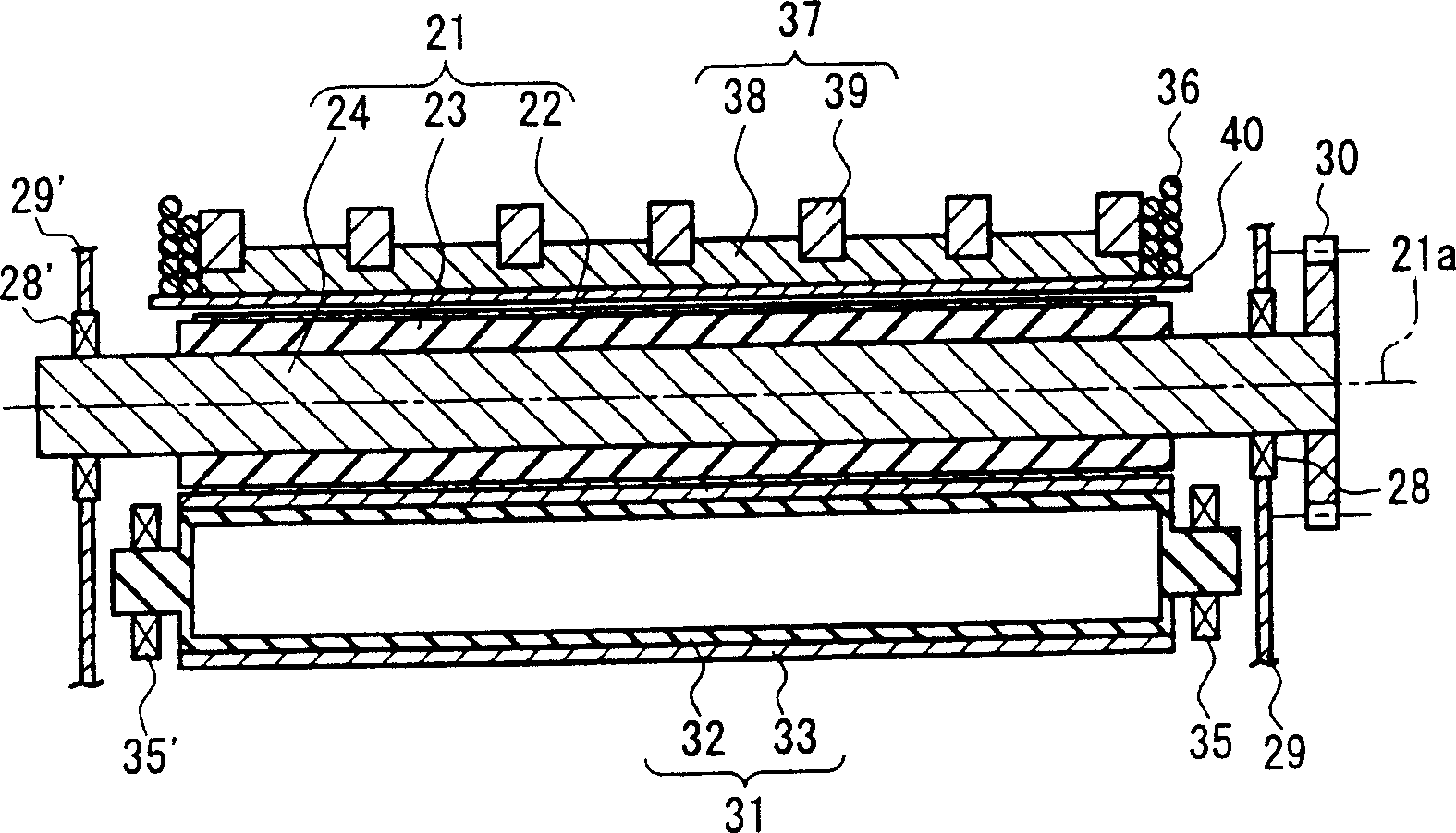
[0068] attached figure 1 Shown is a cross-sectional view of an image heating device used as a fixing device according to Embodiment I-1 of the present invention, which is used in the attached Figure 5 In the above image forming apparatus shown in . attached figure 2 shown from attached figure 1 Structural view of the excitation unit looking in the direction indicated by the arrow II. attached image 3 shown in the attached figure 2 A perspective sectional view taken on the line III-III (a plane including the rotation center axis 21a of the heating roller 21 and the winding center axis 36a of the excitation coil 36). attached Figure 4 Shown is a cross-sectional view of the layered structure of the surface layer portion of the heating roller 21 including the heat generating layer 22 .

[0069] Reference numeral 21 denotes a heating roller, which is composed of a heat generating layer 22 formed of a thin conductive material, a heat insulating layer 23 formed of a mat...

Embodiment I-2

[0112] Then refer to the attached Figure 7 ,8 and 9 describe the image heating device according to Embodiment I-2 as the fixing device. In Embodiment I-2, similar reference characters denote similar components having the same structure and performing the same functions as components in the image heating apparatus described according to Embodiment I-1, and their repetitions are omitted here. describe. In this embodiment, the squeeze roller 31, the exciting coil 36, the rear magnetic core 37, etc. have the same structure as those described according to the embodiment I-1.

[0113] In an example according to the present embodiment, as the heat generating layer 22 , a 40 μm-thick endless strip-shaped material of non-magnetic stainless steel SUS304 formed by plastic processing is used. Although SUS304 is basically non-magnetic, plastic processing still produces magnetism in SUS304. In addition, SUS304 has excellent durability against mechanical deformation as its basic characte...


PUM


Abstract

A heating roller (21) includes a heat generating layer (22) that generates heat by electromagnetic induction, a heat insulating layer (23), and a supporting layer (24), which are provided inwardly in this order. The supporting layer (24) is formed of a material having a specific resistance of 1 x10<-5 >Omegam or higher. Therefore, even when the heat generating layer (22) has a thickness smaller than a skin depth, i.e. a thickness defined by a flow of an induction current, so that magnetic flux penetrates the heat generating layer (22) and even reaches the supporting layer (24), heat generation of the supporting layer (24) under an eddy current can be suppressed. Thus, the heat generating layer (22) can be decreased in thermal capacity, and heat generation of the supporting layer (24) is suppressed, so that only the heat generating layer (22) can be heated efficiently. As a result, a warm-up time can be reduced. Further, breakage by heat of, for example, bearings supporting the heating roller (21) can be prevented.

Description

technical field [0001] The present invention relates to a heating roller heated by eddy current generated by utilizing electromagnetic induction. Furthermore, the present invention also relates to an image heating device suitable for use as a fixing device for thermally fixing an unfixed image by heating in an image forming apparatus such as an electrophotographic apparatus, an electrostatic recording apparatus, and the like. Furthermore, the present invention also relates to an image forming apparatus including such an image heating device. Background technique [0002] Generally, as an image heating device typified by a thermal fixing device, a contact heating type device such as a roller heating type and a belt heating type is generally used. [0003] In recent years, in response to demands for reduced power consumption and shortened warm-up time, roll heating type and belt heating type devices utilizing electromagnetic induction heating have been proposed. [0004] att...

Claims


Application Information

Patent Timeline
Patent Type & Authority Applications(China)
IPC IPC(8): G03G15/20H05B6/14
CPCG03G2215/2029G03G15/2053H05B6/145G03G2215/2025G03G2215/2016G03G2215/2032G03G15/2057
Inventor 今井胜中野雅明渡边周一藤本圭祐井上雅臣片伯部升
Owner PANASONIC CORP
Why Eureka
Try Eureka