Shift gear controlling system of hybrid power vehicle

A hybrid electric vehicle and control system technology, applied in the field of hybrid electric vehicle transmission control system

Active Publication Date: 2004-06-16
TOYOTA JIDOSHA KK
View PDF2 Cites 19 Cited by
  • Summary
  • Abstract
  • Description
  • Claims
  • Application Information

AI Technical Summary

Problems solved by technology

[0004] However, there is a problem that, when the clutch is disengaged, if control occurs so that the output torque of the motor compensates for the decrease in the torque transmitted to the wheels by driving the motor with electric power from the battery, the power supply to the motor is limited. A power source, such as a battery, has to be increased in its capacity and size, as disclosed in Japanese Patent Laid-Open No. 11-141665

Method used


Image

  • Shift gear controlling system of hybrid power vehicle
  • Shift gear controlling system of hybrid power vehicle
  • Shift gear controlling system of hybrid power vehicle

Examples


Embodiment Construction

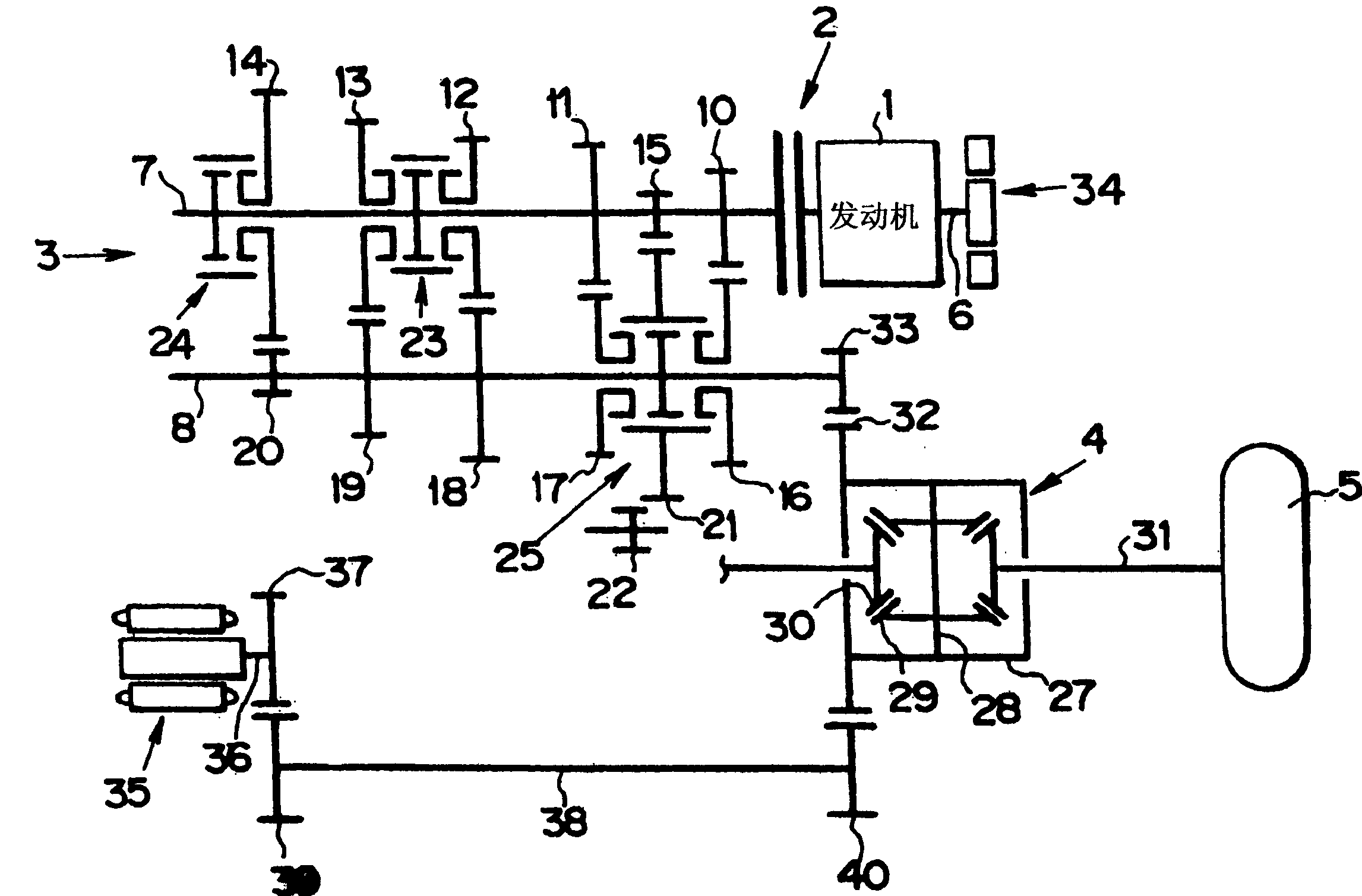
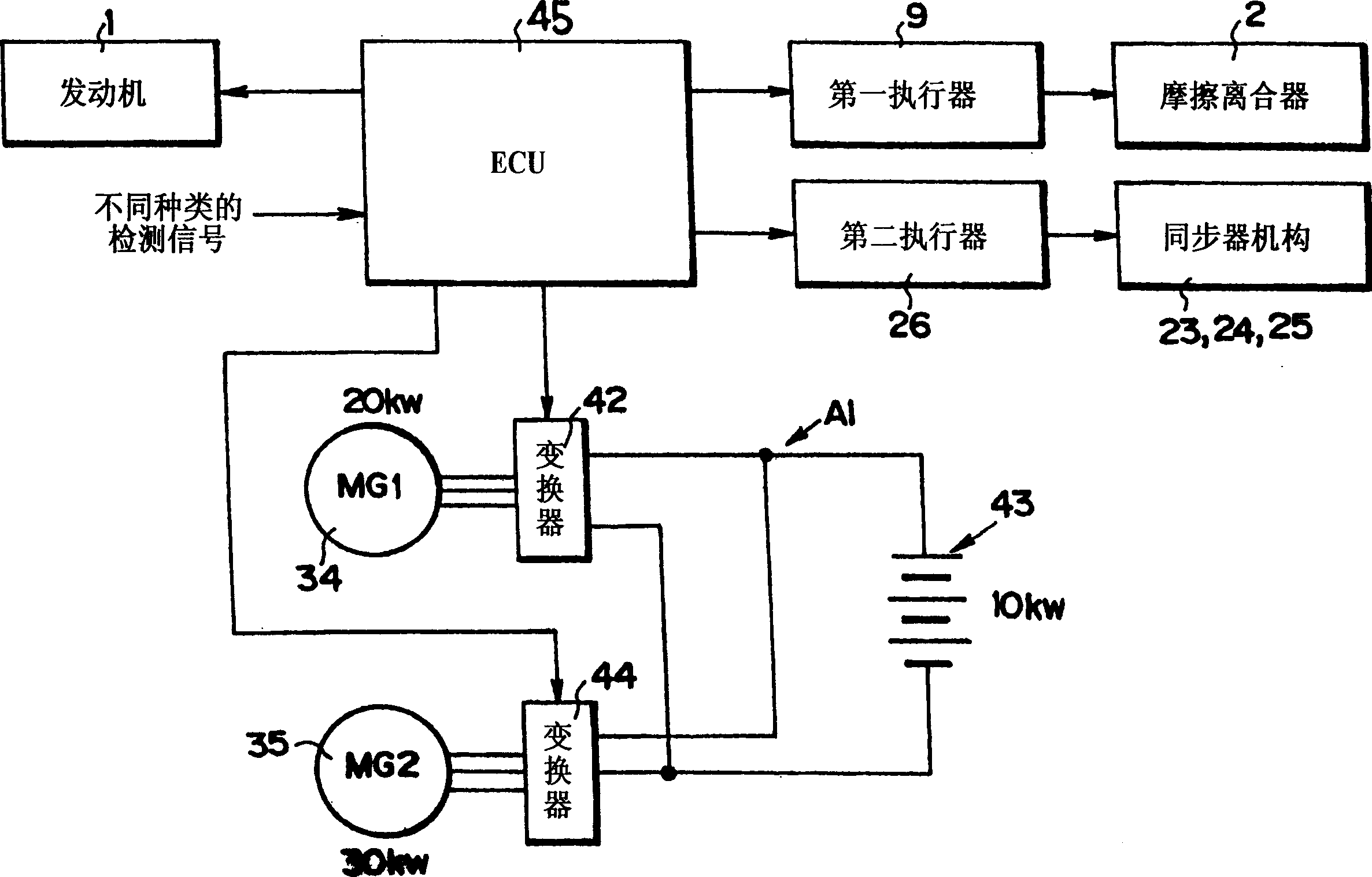
[0015] Hereinafter, the present invention will be described with reference to specific examples. An example of the drive train of the vehicle (hybrid vehicle) Ve to which the present invention is applied is as follows figure 2 As shown, the control system and electrical system of the vehicle Ve are as follows image 3 shown. according to figure 2 The power train shown is configured to transmit the torque of the prime mover 1 to the wheels (front wheels) 5 via the clutch 2 , the transmission 3 and the differential 4 . The clutch 2 is composed of a friction clutch, an electromagnetic clutch, a magnetic powder clutch, and the like. The prime mover 1 is constituted by, for example, an internal combustion engine, particularly any of a gasoline engine, a diesel engine, a liquefied petroleum gas (LPG) engine, and the like. Hereinafter, a case where a gasoline engine is used as the prime mover 1 will be described, and the prime mover 1 will be referred to as "engine 1" for brevity...


PUM


Abstract

The system has a clutch mechanism arranged between a principal motor and a transmission in which its coupling capacity is diminished during a transmission ratio change. An electric motor supports a driving couple during the ratio change. An electronic circuit drives the electric motor by electric power produced by an electric power generator during the ratio change of the transmission.

Description

technical field [0001] The present invention relates to a system for controlling shifting of a transmission in a hybrid vehicle provided with an electric motor as a prime mover in addition to an internal combustion engine, etc. A hybrid that transmits to the wheels. Background technique [0002] In a vehicle, a clutch and a transmission are provided between the engine and the vehicle, and a control for reducing the maximum torque of the clutch when the transmission shifts gears is known in the prior art. However, when the maximum torque of the clutch is thus lowered when the transmission is shifted, there is a problem that the driving torque or acceleration fluctuates due to the lowered torque transmitted to the wheels. In this regard, there is known a technique capable of suppressing torque or acceleration even when the maximum torque of the clutch decreases when the transmission shifts, an example of which is disclosed in Japanese Patent Laid-Open No. 11-141665. [0003]...

Claims


Application Information

Patent Timeline
Patent Type & Authority Applications(China)
IPC IPC(8): B60W20/00B60K1/02B60K6/24B60K6/26B60K6/36B60K6/387B60K6/40B60K6/442B60K6/547B60L50/16B60W10/00B60W10/04B60W10/06B60W10/08B60W10/10F16H3/089F16H61/04
CPCB60K2006/4808F16H2003/0818Y02T10/6234F16H61/0437Y02T10/626B60K6/547B60K6/442B60W10/08B60K1/02F16H2061/0433F16H61/682F16H3/089Y02T10/6221B60W30/19F16H63/502B60K6/48Y02T10/62
Inventor 米田修佐佐木静夫桥本佳宜村田宏树北村雄一郎铃木良英
Owner TOYOTA JIDOSHA KK
Why Eureka
Try Eureka