Plate display producing apparatus

A technology for flat panel displays and manufacturing devices, applied in semiconductor/solid-state device manufacturing, manufacturing tools, transportation and packaging, etc., capable of solving problems such as substrate 40 fracture, impossible substrate, substrate 40 bending, etc.

Inactive Publication Date: 2004-06-23
ADVANCED DISPLAY PROCESS ENG
View PDF0 Cites 7 Cited by
  • Summary
  • Abstract
  • Description
  • Claims
  • Application Information

AI Technical Summary

Problems solved by technology

In the case where the large-area substrate 40 is lifted and transferred by being supported only by its peripheral portion as in the conventional method, severe bending occurs at the central portion of the substrate 40, so that the substrate 40 may break
In addition, there is a serious problem that the transfer of the substrate will not be possible because the manipulator cannot be inserted under the substrate 40.

Method used


Image

  • Plate display producing apparatus
  • Plate display producing apparatus
  • Plate display producing apparatus

Examples


no. 1 example

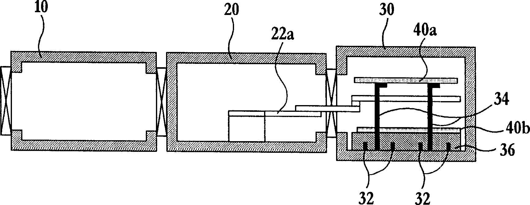
[0048] Figure 4 is a plan view for explaining a flat panel display manufacturing apparatus according to the first embodiment of the present invention.

[0049] refer to Figure 4 , the flat panel display manufacturing apparatus includes two chambers, ie, the transfer chamber 120 and the process chamber 130, unlike a conventional flat panel display manufacturing apparatus including three chambers. In the transfer chamber 120, a single robot 122 for transferring a substrate and a vacuum pump (not shown) are provided.

[0050] A substrate to be processed enters the process chamber 130 through the transfer chamber 120 from the outside by the operation of the robot 122 and the gate valves 125a and 125b. The process-completed substrate is discharged from the process chamber 130 to the outside through the transfer chamber 120 by the operation of the robot 122 and the gate valves 125a and 125b.

[0051] In the process chamber 130, a substrate support plate 136 mounting a substrate...

no. 2 example

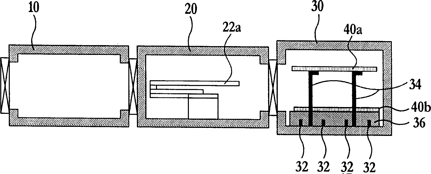
[0066] Image 6 is a plan view for explaining a flat panel display manufacturing apparatus according to a second embodiment of the present invention.

[0067] refer to Image 6 , the flat panel display manufacturing apparatus includes two chambers, ie, the transfer chamber 220 and the process chamber 230, unlike a conventional flat panel display manufacturing apparatus including three chambers. In the transfer chamber 220, a single robot 272 for transferring a substrate and a vacuum pump (not shown) are provided.

[0068] The substrate to be processed enters the process chamber 230 through the transfer chamber 220 from the outside by the operation of the robot 272 and the gate valves 225a, 225b. The process-completed substrate is discharged from the process chamber 230 to the outside through the transfer chamber 220 through the operation of the robot 272 and the gate valves 225a, 225b. In the process chamber 230, a substrate support plate 236 on which a substrate to be proc...

no. 3 example

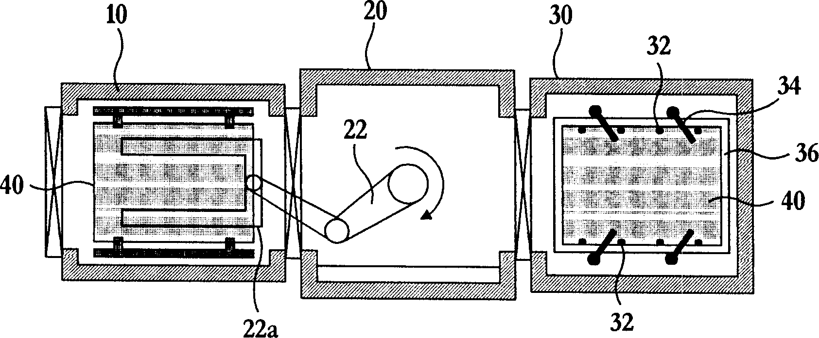
[0082] Figure 8 is a plan view for explaining a flat panel display manufacturing apparatus according to a third embodiment of the present invention.

[0083] refer to Figure 8 , a flat panel display manufacturing apparatus includes two chambers, ie, a transfer chamber 320 and a process chamber 330, unlike a conventional flat panel display manufacturing apparatus including three chambers. In the transfer chamber 320, a single robot 322 for transferring a substrate and a vacuum pump (not shown) are provided.

[0084] The substrate to be processed enters the process chamber 330 through the transfer chamber 320 from the outside by the operation of the robot 322 and the gate valves 325a, 325b. The process-completed substrate is discharged from the process chamber 330 to the outside through the transfer chamber 320 by the operation of the robot 322 and the gate valves 325a, 325b.

[0085] In the process chamber 330, a substrate support plate 336 on which a substrate to be proce...


PUM


Abstract

An FPD fabricating apparatus according to the present invention comprises two chambers of a process chamber 130 and a transfer chamber 120. The substrate 140 is mounted on and transferred by one of two carrier plates 150a and 150b, each of which have a forked shape. The carrier plate lift pins 160b are raised up and fallen down while avoiding contact with the forked prongs of the robot arm 122a, so that the carrier plates 150a and 150b can be raised up and fallen down. The substrate lift pins 160a which are raised up and fallen down while avoiding contact with all the forked prongs of the robot arm 122a and the carrier plates 150a and 150b, so that only the substrate 140 mounted on the carrier plates 150a and 150b can be raised up and fallen down. According to the present invention, a load-lock chamber for transferring a substrate and a transfer chamber is incorporated into a single transfer chamber, so that space of the apparatus can be remarkably reduced and cost of the apparatus can be reduced. In addition, since the substrate is raised up and fallen down by using the carrier plates 150a and 150b, even large-area substrate can be stably transferred at high speed without bending, disrupting or vibration of the substrate.

Description

field of invention [0001] The present invention relates to a flat panel display (hereinafter referred to as a flat panel display) manufacturing apparatus, and more particularly, to a device capable of combining a load lock chamber and a transfer chamber for transferring substrates into a single transfer chamber and capable of transferring A flat panel display manufacturing device that prevents large-area substrates from bending. Background of the invention [0002] Generally, a flat panel display manufacturing apparatus, such as a dry etcher, a chemical vapor deposition apparatus, and a sputtering machine, includes three vacuum chambers. The three vacuum chambers are the charge lock chamber, the process chamber, and the transfer chamber. The load lock chamber is used to receive substrates to be processed from the outside and discharge processed substrates to the outside. The process chamber is used to perform a thin film deposition process, an etching process, etc. by usin...

Claims


Application Information

Patent Timeline
Patent Type & Authority Applications(China)
IPC IPC(8): B65G49/06C23C14/56C23C16/44H01L21/677H01L21/687H01L27/12
CPCC23C14/566H01L21/68778H01L21/67748H01L27/12H01L21/68742
Inventor 许光虎李哲源崔浚泳安贤焕
Owner ADVANCED DISPLAY PROCESS ENG
Why Eureka
Try Eureka