High frequency oscillation type proimity sensor

A technology of proximity sensor and high-frequency oscillation, which is applied in the direction of power oscillators, instruments, scientific instruments, etc., and can solve problems such as large components

Inactive Publication Date: 2004-07-28
YAMATAKE HONEYWELL CO LTD
View PDF2 Cites 13 Cited by
  • Summary
  • Abstract
  • Description
  • Claims
  • Application Information

AI Technical Summary

Problems solved by technology

[0010] However, when constructing a soft oscillation circuit that strives to stabilize the above-mentioned operating characteristics and at the same time meet the requirements of extending the detection distance, for example, the above-mentioned feedback circuit must be used to cancel the dependence of the copper resistance Rcu of the detection coil on temperature. On the one hand, it is necessary to change the oscillation amplitude of the high-frequency oscillation circuit according to the change of the Q value of the detection coil, so that there is a problem that its configuration becomes too large.

Method used


Image

  • High frequency oscillation type proimity sensor
  • High frequency oscillation type proimity sensor
  • High frequency oscillation type proimity sensor

Examples


Embodiment Construction

[0033] The high-frequency oscillation type proximity sensor according to the embodiment of the present invention, especially

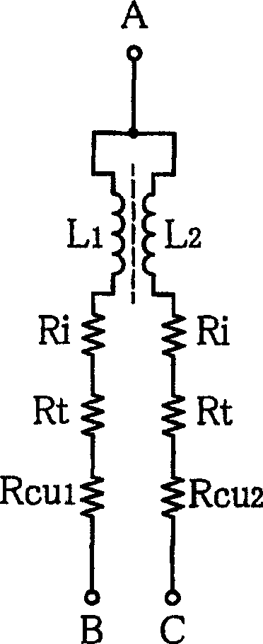
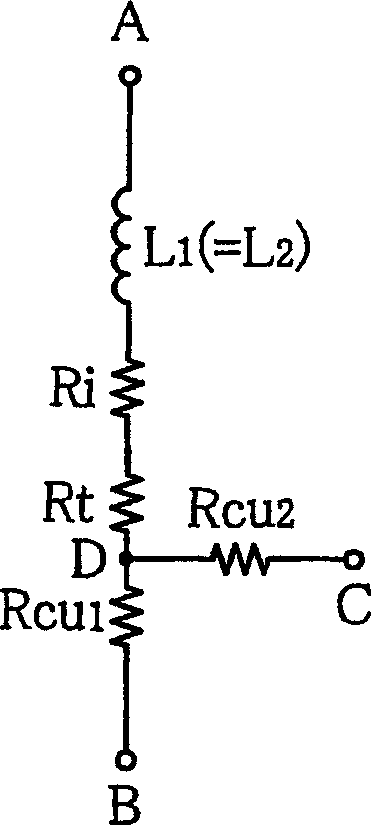
[0034] The compensation device for compensating for the copper resistance of the detection coil will be mainly explained.

[0035] (first embodiment)

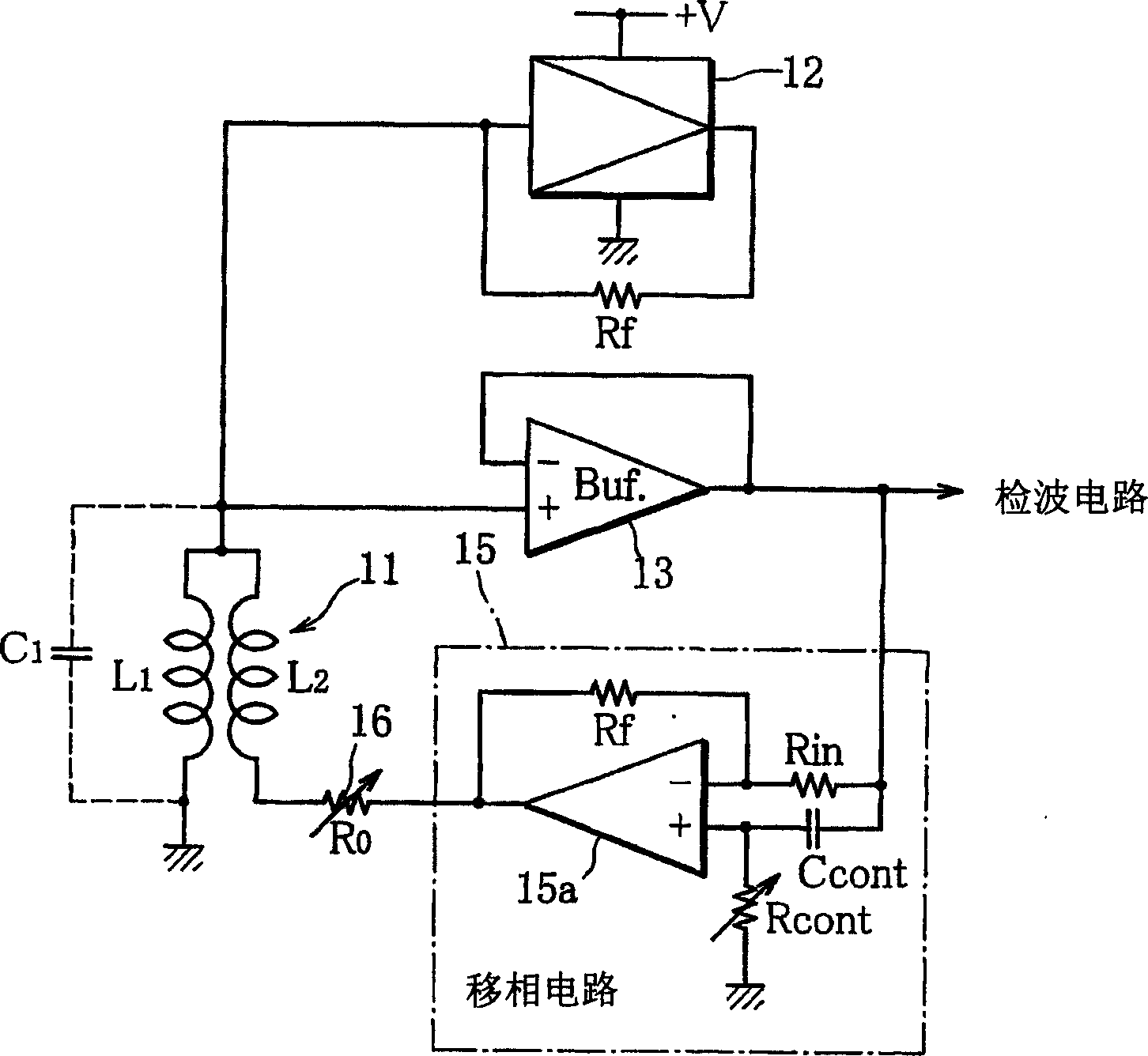
[0036] figure 1 It is a schematic configuration diagram of main parts of the high-frequency oscillation type proximity sensor according to this embodiment, and 11 is a detection coil constituting a part of the high-frequency oscillation circuit. The detection coil 11 is a bifilar coil, for example, by twisting two high-frequency litz wires (coil conductors) L1 and L2 connected in common at one end and winding them on a resin coil frame (not shown). . Also, for example, a ferrite core (not shown in the figure) may be inserted into the bobbin. One coil L1 of the bifilar coils is used as a coil for a resonant circuit forming an LC parallel resonator between capacitors C1 connected in parallel to the co...


PUM


Abstract

A high-frequency oscillation proximity sensor with an improved detection sensitivity uses, as a detection coil 11, a two-thread coil formed of substantively two coil conductors joined together at their first ends to form a joint connection end and twisted together, one of the two coil conductors being used as a resonance circuit coil L1 and the other as a copper resistance compensation coil L2, and comprises a drive circuit 12 for supplying a drive current to the joint connection end of the two-thread coil to thereby drive the detection coil to oscillate, a buffer 13 for taking out an oscillating output voltage generated at the joint connection end of the two-thread coil, and a phase shift circuit 15 for turning the phase of the oscillating output voltage taken out by the buffer by a predetermined angle and feeding it back to the copper resistance compensation coil to thereby negate the copper resistance of the two-thread coil. The drive circuit comprises a nonlinear amplifier 21 for changing the amplitude of the oscillating voltage generated at the two-thread coil in multiple stages to thereby impart a soft oscillation characteristic to a high-frequency oscillation circuit comprising the nonlinear amplifier and the two-thread coil.

Description

technical field [0001] The present invention relates to a method for detecting an approaching object by utilizing a change in the oscillating output voltage (amplitude) of the high-frequency oscillating circuit caused by electromagnetic induction between a detection coil constituting a part of the high-frequency oscillating circuit and an object to be detected. High-frequency oscillation type proximity sensor for the detection object. [0002] Especially the present invention relates to such a kind of high-frequency oscillation type proximity switch, and its described detecting coil is actually made of two twisted coil conductors connected in common at one end, and one of the coils is used as a coil for a resonant circuit, At the same time, the other coil serves as a coil for internal resistance compensation. Using this bifilar coil, the internal resistance component (so-called copper resistance component) thereof is virtually (equivalently) short-circuited to improve detectio...

Claims


Application Information

Patent Timeline
Patent Type & Authority Applications(China)
IPC IPC(8): G01V3/10
CPCG01V3/10
Inventor 林巧川井真一畑中浩
Owner YAMATAKE HONEYWELL CO LTD
Why Eureka
Try Eureka