Motorised valve

A technology of electric valve and valve body, which is applied in the direction of lifting valve, valve device, valve details, etc. It can solve the problems that are not easy, not particularly difficult, difficult, etc., and achieve the effects of stable installation state, easy manufacturing, and simplified composition

Inactive Publication Date: 2004-08-11
FUJIKOKI MFG CO LTD
View PDF1 Cites 8 Cited by
  • Summary
  • Abstract
  • Description
  • Claims
  • Application Information

AI Technical Summary

Problems solved by technology

[0006] Thereafter, in order to update or replace the drive unit 10, the refrigerant pressure may be applied to the electric valve A. In this state, the drive unit 10 may be detached from the valve body unit 20 or installed. However, In this case, it is not particularly difficult if the refrigerant pressure is low. In addition, when detaching the drive unit 10 from the valve body unit 20, since it is performed by loosening the nut 26 and separating it together with the nut 26, this Homework is not particularly difficult
[0007] However, when the refrigerant pressure is high, when the drive unit 10 is separated from the valve body unit 20, the bellows 33 will shrink due to the refrigerant pressure, and the valve body 30 will move upward as shown in FIG. 21 protruding above
Moreover, in this state, when the drive unit 10 is installed on the valve body unit 20 again, the operator needs to position the drive unit 10 on the upper part of the valve body unit 20, overcome the high refrigerant pressure, and place the valve body 30 It is very difficult to install while turning the nut 26 in the state of pushing down.

Method used


Image

  • Motorised valve
  • Motorised valve
  • Motorised valve

Examples


Embodiment 1

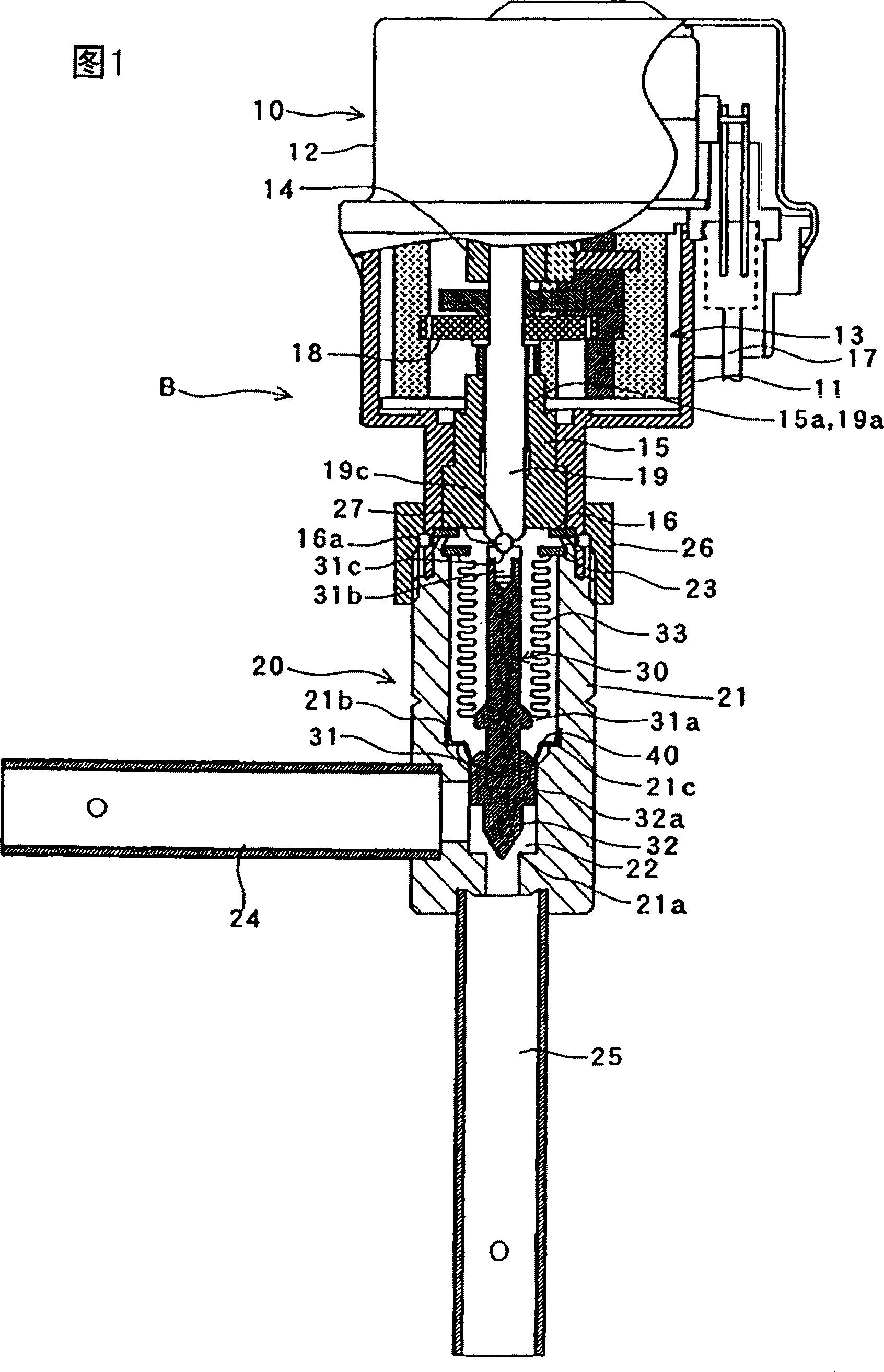
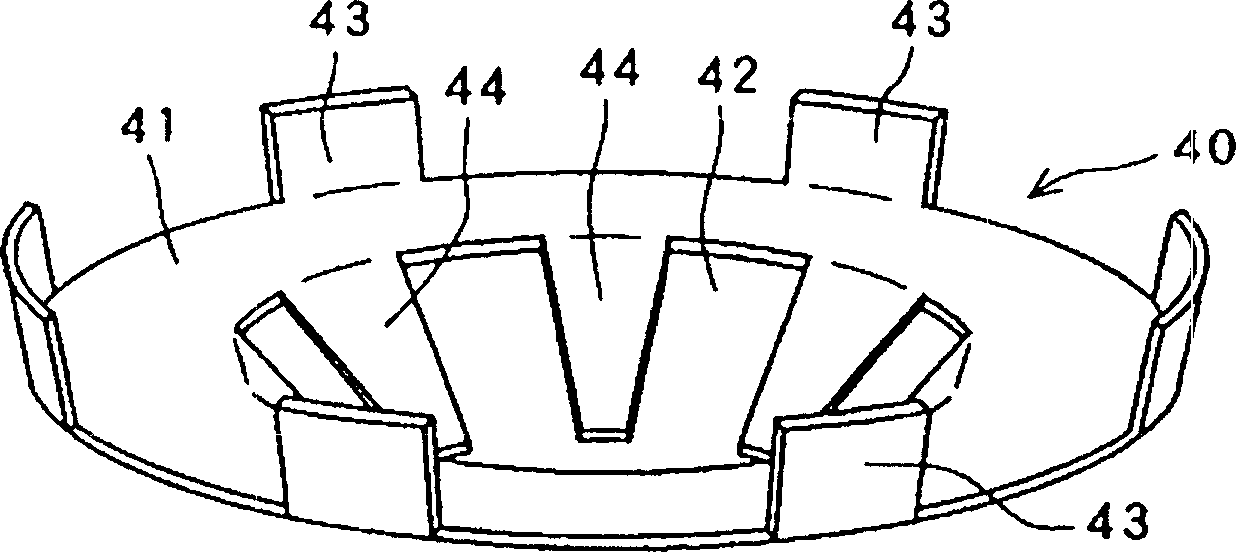
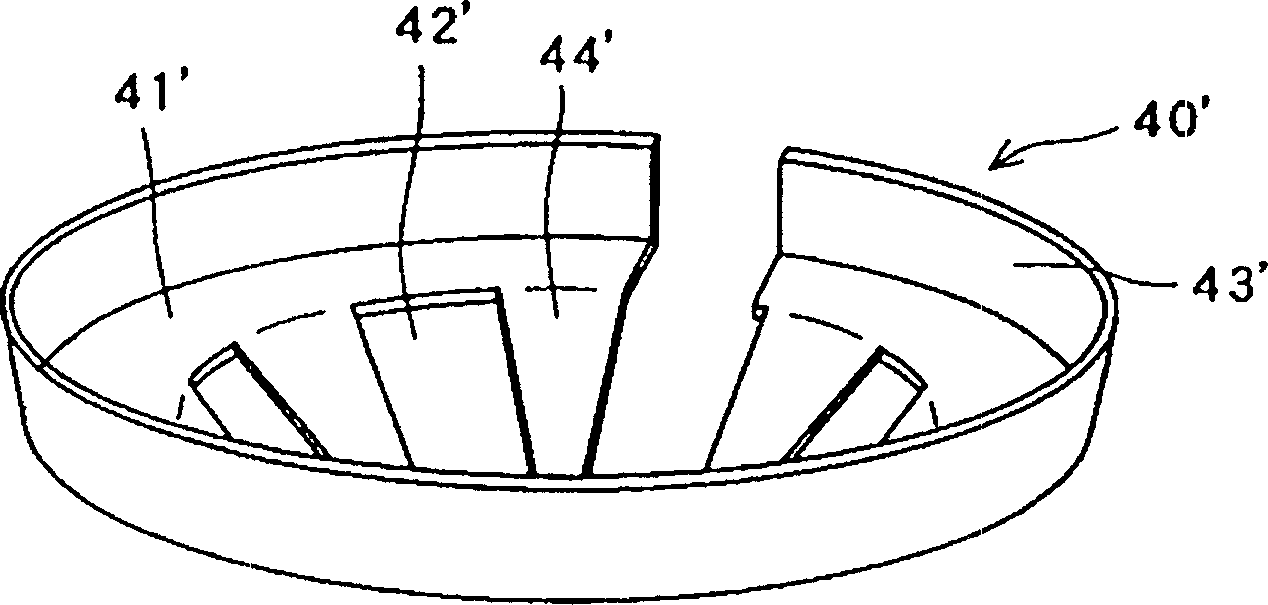
[0036] Embodiment 1 of the electric valve of the present invention will be described below with reference to the accompanying drawings. Fig. 1 is a schematic partial longitudinal sectional view thereof. figure 2 is a perspective view of its main part (stopper). image 3 is a perspective view of another form of its main part (stopper). Figure 4 It is an explanatory diagram of the function of the main part (stopper).

[0037] The electric valve B is composed of a drive unit 10 and a valve body unit 20 .

[0038] First, the drive unit 10 will be described. The drive unit 10 is constituted by a stepping motor (no symbol) mounted on a case body 11 , a motor case 12 covering the stepping motor, and the like. The stepper motor is provided with leads 17 . A reduction mechanism 13 composed of various gears is disposed on the lower portion of the housing body 11 .

[0039] The reduction mechanism 13 is driven by a stepping motor, and is transmitted to an output rotary shaft 19 th...

Embodiment 2

[0057] Next, Embodiment 2 of the present invention will be described. Figure 5 It is a longitudinal sectional view of its main part, and on the same constituent parts as the above-mentioned embodiment 1, in Figure 5 The winning mark is the same as that in Figure 1~ Figure 4 The referenced symbols are the same symbols, and therefore, description thereof will be omitted.

[0058] In Embodiment 2, when the valve body 30 moves upward and protrudes above the valve body 21, the contact portion 32b of the valve 32 that is in contact with the stopper 40 is not provided with the engaging step 32a as in Embodiment 1, but is in contact with the stopper 40. A sloped flat face with the same other faces. According to the structure of the second embodiment, the structure of the valve 32 is simple and can be processed easily. In addition, in Embodiment 2, the lower edge of the portion 44 of the stopper 40 that contacts the valve body (the contact surface to the contact portion 32b of th...

Embodiment 3

[0061] Below, with regard to embodiment 3 of the present invention, illustrate, Image 6 It is the longitudinal sectional view of its main part. Figure 7 is to further enlarge Image 6 Sectional view of main parts. Figure 8 is an enlarged sectional view of the stopper 50 . In addition, in Embodiment 3, in terms of the same constituents as in Embodiment 1 above, in Figure 6 ~ Figure 7 The winning mark is the same as that in Figure 1~ Figure 4 The referenced symbols are the same symbols, and therefore, description thereof will be omitted.

[0062] On a portion of the inner surface of the valve body 21, an attachment recess C for a stopper 50 to be described later is formed. The mounting recess C is composed of an upper fitting step 21b, a back support portion 21d and a lower fitting step 21e below the back support portion 21d. The back support portion 21d is continuous with the upper fitting step 21b, and has a uniform inner diameter substantially parallel to the inner...


PUM


Abstract

To easily mount and demount a driving part and a valve element part. In this electric valve A which is composed of the driving part 10 and the valve element part 20 and wherein the valve element 30 mounted on the valve element part 20 is energized in a state of being projectable to a driving part 10 side by refrigerant pressure, a stopper 40 is mounted between a valve main body 21 and the valve element 30 for inhibiting the projection of the valve element 30, when the driving part 10 and the valve element part 20 are separated from each other. The stopper 40 is mounted between the valve main body 21 and a valve part 32 constituting the valve element 30. The stopper 40 comprises a main body contact part 43 and a valve element contact part 44, composed of an elastic material, the main body contact part 43 is locked on an inner face of the valve main body 21, and the valve element contact part 44 is locked on an outer peripheral part of the valve part 32.

Description

technical field [0001] The present invention relates to electric valves suitable for refrigerating cycles, etc., and more specifically, relates to electric valves suitable for controlling the flow of refrigerant in air conditioners or controlling the flow of combustion gas, air, warm water, liquid fuel, etc. in baths and showers. valve. Background technique [0002] Conventional electric valves generally consist of a valve body unit and a drive unit, both of which are detachable. This type of electric valve is described in, for example, the following patent document 1: Japanese Patent Application Laid-Open No. 11-82796. [0003] Next, the electric valve A described in this patent document 1 will be described with reference to FIG. 10 . The driving unit 10 is composed of a stepping motor, a reduction mechanism, etc., and is used to rotationally drive the output rotary shaft 19 . This rotational driving motion is converted into the vertical motion of the output rotary shaft 1...

Claims


Application Information

Patent Timeline
Patent Type & Authority Applications(China)
IPC IPC(8): F16K31/04F16K35/00F25B41/06
CPCF25B2341/065F25B41/062Y02B30/72Y02B30/70F25B41/34F25B41/35F16K31/04
Inventor 铃木教郎樋口浩次梅泽仁志
Owner FUJIKOKI MFG CO LTD
Why Eureka
Try Eureka